
You are using an out of date browser. It may not display this or other websites correctly.
You should upgrade or use an alternative browser.
You should upgrade or use an alternative browser.
ALWSR Build Thread
- Thread starter timH
- Start date
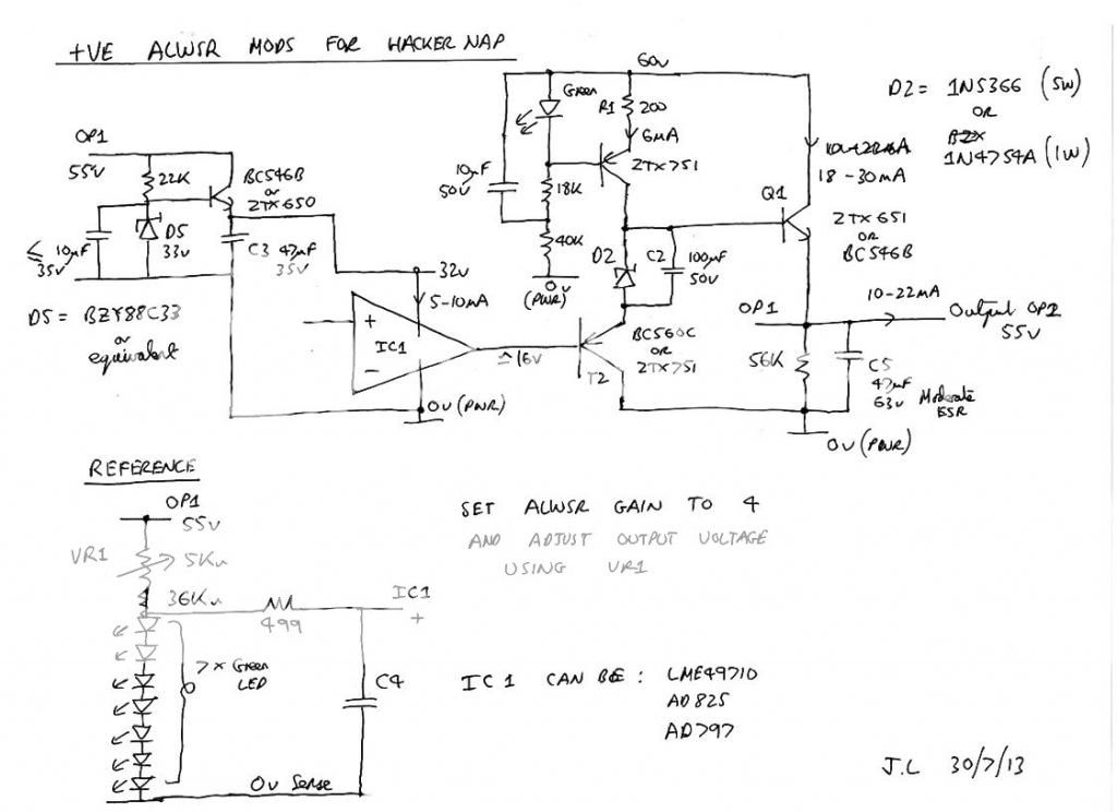
Oh and I’ve just used a green led for D6 (r3 position)
...but you want 55V at the output? I wonder how many LEDs in the reference string are needed and what is best to put in R3 if VIN at the TPR is 56V and I want 40V at the output...
Last edited:
I’ve no idea - we need an expert. I’m just a follower.
") me too...!
me too...!It’s key where you cut the track from OP1. It needs to be between OP1 and C3+ rather than between C3+ and Opamp pin 7
thanks, corrected!
Here's an outline of what I did on my Hackernap.

Hi John, I frankly used your above diagram for my schematic because you marked my post #91 with a "like". I added the pre tracking regulator (with a probably wrong zener in R3) and changed the 7x LED string to 5x and hope that's correct for the desired 40V output, but am not sure about that. Please have a brief look to the schematic in #97 and let me know if I have errors in it.
Currently struggling with soldering together 7 x smd green leds for the voltage ref
Tim, did you already complete your 55V build?
Tim, did you already complete your 55V build?
Just waiting on one part. Here’s a pic so far

john.luckins
pfm Member
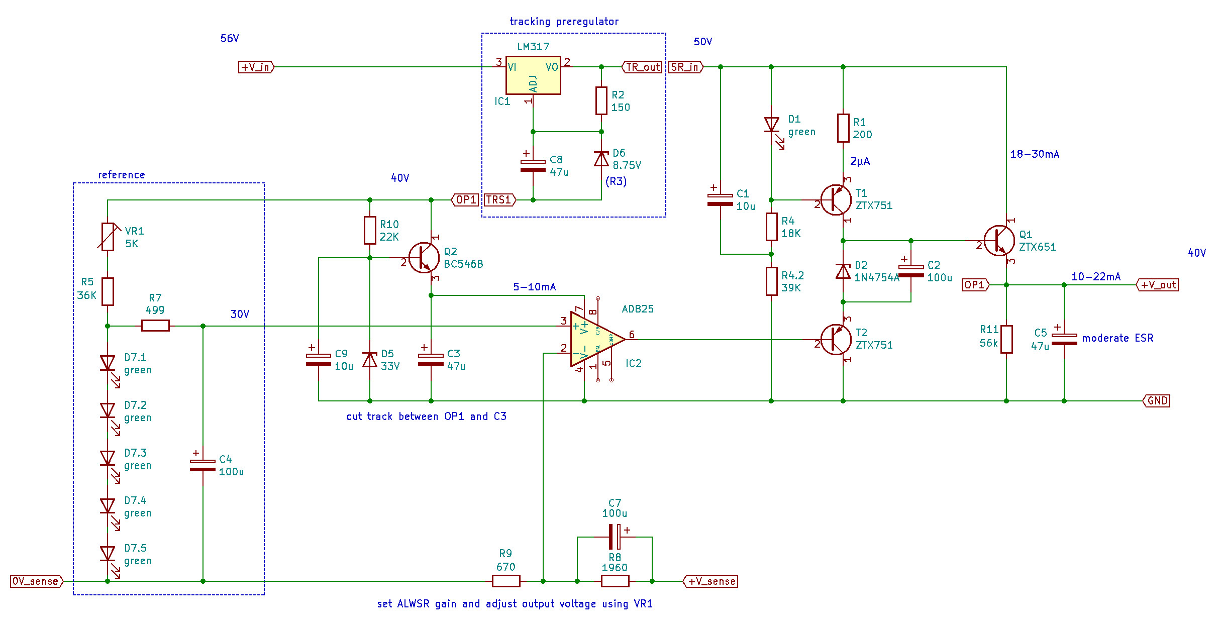
OK, I put together a schematic, inspired from here, for a 40V version as a drop in replacement for the regulator board in Naim style power amps to power the front end (when running the power stage from a raw PSU):
Hi jpk et al,
I don't have much time so can't yet draw suggested changes to the above schematic, but here's what I would do to improve it if it is going to become a new regulator board. I have always made my changes with point to point wiring on the ALWSR boards but that is messy for this HV one and is difficult to mount safely.
- Firstly I would heartily recommend replacing the AD825 with an OPA1611. The main reason is it's better phase margin and I have the measurements to back that up. It is very nearly as good as an AD797 but without the stability worries.
- I have changed the cap multiplier design around your Q2 to improve its filtering/stability and lower its noise. R10 needs to be changed to a constant current source of >1mA. J505-J507's are available from ebay. If you simply cannot get any CCS's then reduce R10 to 6k8 to get enough current flowing through the zener. A 10k and a 100-200 ohm resistor should be placed in series between the anode of D5 and the base of Q2, The anode of C9 should be connected to the junction of these two new resistors. The cathode of C9 can stay put. I prefer a Wima MKS 10uF to an electrolytic here. That gives you much more effective filtering of the zener and a base stopper resistor to guarantee emitter follower stability.
- The output (emitter) of Q2 can also feed the reference with 33volts (rather than 40 volts). The extra filtering makes a noticeable difference.
- The reference can be altered to improve its rejection with the addition of a single transistor and resistor but perhaps that is for later. You do however need more current going through the LED string, at least 1 mA, so reduce R5 to 20k.
- The LED string should give approx 9 volts so you need a gain of roughly 4.4. I would suggest making R9 620 ohms and R8 2k2 ohms which gives you gain of 4.54 , leading to an output of 40.9 volts.
- D6 can be replaced by 2 red or green LED's and will be quieter as a result and R2 should be reduced to 240 ohms to give roughly 5mA through these LED's to the load.
- C1 should be a 35 volt part and R4 and R4.2 should really be the same value and be between 15k and 20k. 20k is best.
- C9 and C5 should be 50 volt parts.
- Finally you can dispense with VR1 as the output voltages don't have to be precise. If you want precise it is better to feed 32.4 volts if you have it into the 20k R5 and the diode string you are going to use and measure its actual voltage. You can then work out the gain you need and the resistor values that will get you close enough using the calculations on the schematic page of the ALWSR manual. Alternatively you can run the device on a resistive load with the values given and measure the diode string voltage at that time, adjusting R8 and R9 accordingly.
Bon chance
John
john.luckins
pfm Member
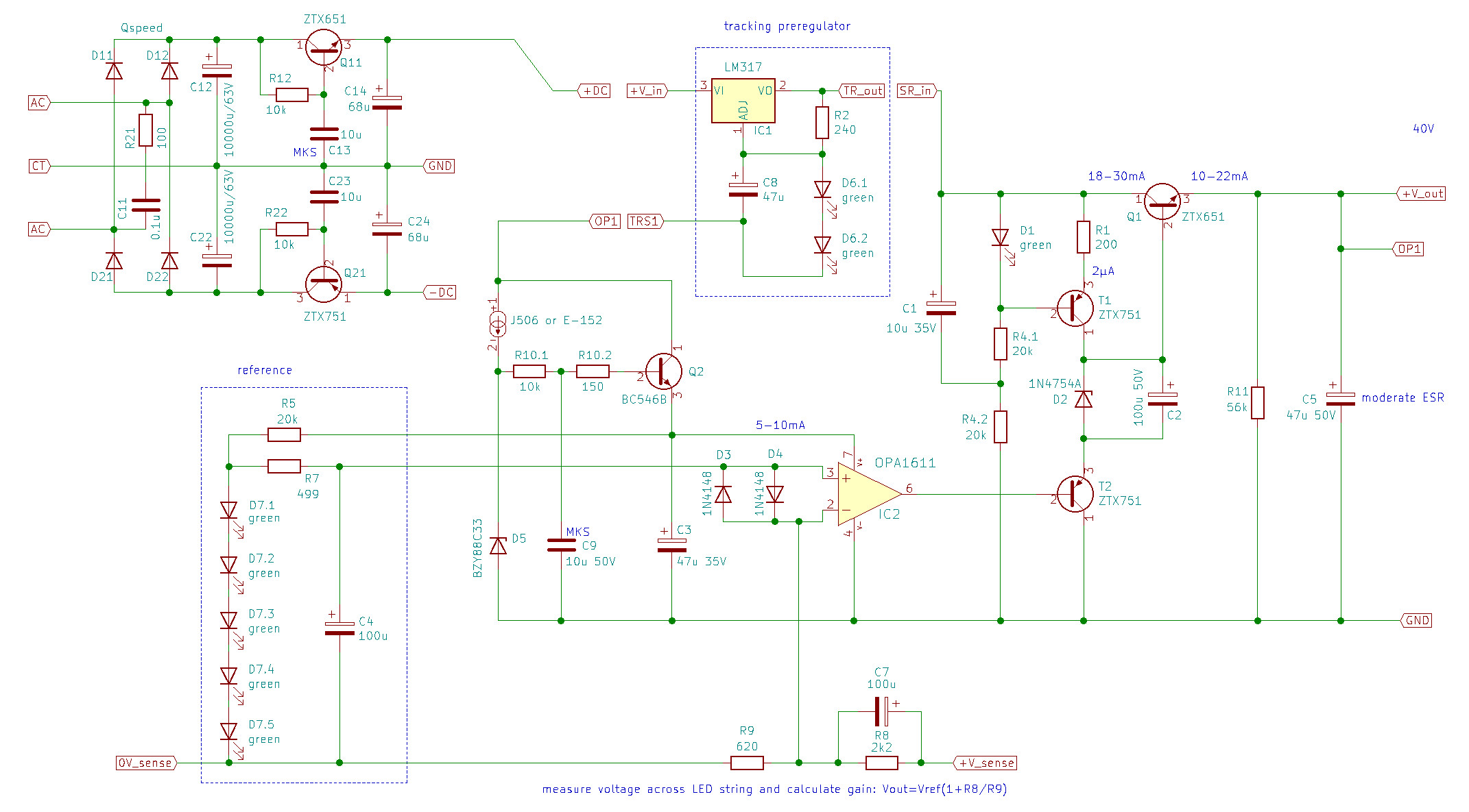
John, many thanks, great instructions! I upgraded the schematic with your suggestions:
Can I also use the E-152 instead of the J506? I want to use the board for a NAP clone (and might try it on an original Naim too), so for the negative rail I also would need some regulating...
All good apart from the cap multiplier around Q2. An E152 will be fine and easier to source, Mouser have some. The R10.1 and R10.2 should connect the cathode of the J506/E152 to the base of Q2. Also connected to this cathode should be the anode of D5 leading to 0v. C9 should then be placed between the junction of R10.1 and R10.2 and 0v. The CCS therefore drives current into the zener D5 and R10.1 only. R10.1 then filters the zener voltage in conjunction with C9 and then R10.2 is just the base stopper resistor for the base of Q2 preventing any tendency to oscillate.
FWIW I have a negative super-reg on my HackerNAP of the same design. It was less beneficial then the one on the positive rail when I fitted it but still an audible improvement. Even a slow start up cap multiplier such as the Fetlington might do and can be made to switch on at roughly the same rate as the positive reg. Mine have both been running for nearly 5 years and the combo with the HackerNAP has allowed me to concentrate on improving my source components, I like it a lot..
John
All good apart from the cap multiplier around Q2
Thanks for helping, I edited the schematic in above posting and hope I got it right. Please alarm if there are still mistakes!
FWIW I have a negative super-reg on my HackerNAP of the same design.
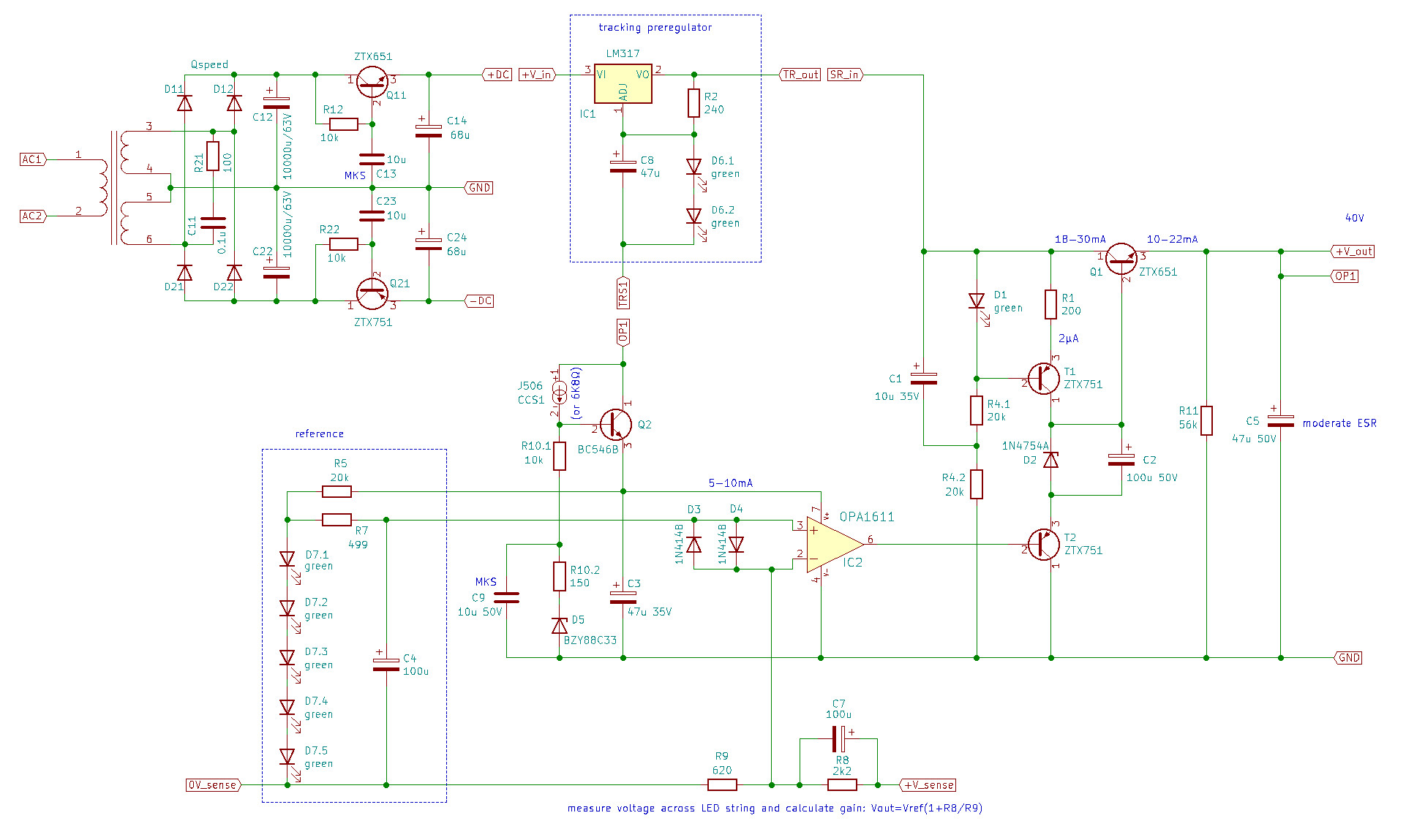
OK, I will make the negative version as soon as I have it all right. Already started with some basic layout (the TO220s are the rectifier diodes). The big PCB can be broken into individual circuits (hence so many mounting holes):
Last edited:
The reference can be altered to improve its rejection with the addition of a single transistor and resistor but perhaps that is for later
John, I would like to include these 2 parts as I have some space left over for them in the upper left area. Here is my first attempt of a PCB layout for the positive version (EDITED: no space left over):
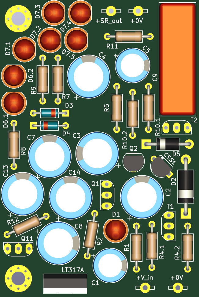
No crossings, all tracks are on the backside, also the opamp. Should I hard wire V_sense -> SR-out, TR_out -> SR_in and 0V_sense -> GND or is it good to keep the separate connectors as drawn? Also should I add a ground plane?
Last edited:
john.luckins
pfm Member
Hi jpk,
If you don't want to use remote sense then hard wiring those three connections is the way to go. Remote sense is of less value when the source cap bank and load are so close to the regulator. A ground plane will result in a lower impedance ground but less control of ground current paths, not a big issue at audio frequencies and low currents, so I suggest you should insert one and get some benefit from the copper you would otherwise waste.
The five LED's have a combined impedance of more than 100 ohms (compared with something like a TL431 which is circa 1 ohm). There is no data on how linear their impedance is or whether it changes with frequency. Their noise is however much lower. Adding a PNP and a 620 ohm resistor can reduce the AC impedance to about 7 ohms but more current will be drawn, about 5 mA. If the reference is being fed from a fixed voltage as yours is then your R5 will have to reduced by a factor of 5 to supply enough current for the new reference. So in theory you would end up with a factor of three increase in rejection. However I'm not convinced it is worth the trouble given you already have a cap multiplier feeding the reference chain. I have tried to see if I can hear the difference made by adding the resistor/PNP combo and I honestly can't say that I can when a cap multiplier has been used. For that reason in this application I wouldn't use it. In lower voltage applications i.e. 5v supplies when there is no voltage headroom for a cap multiplier then I know I can hear its benefit.
Sorry to have dangled the carrot and then so cruelly ripped it away!
John
Hi jpk, what cap are you using for C9?
That's the MKS John recommended!
Also would it be possible to make space for 7 leds for those wanting higher voltages
I think it's possible to choose LEDs with a different forward voltage. Maybe John can confirm? For 9V on the LED string you would need 5x 1.8V, so if you need 12V you can use 5x 2.4V LEDs.
Sorry to have dangled the carrot and then so cruelly ripped it away!
No problem, thanks! I have updated the PCB in #111: deleted the connectors and arranged everything even tighter, so the board is 70mm long and 50mm wide (ALWSR = 70x35mm) even though I included the cap multiplier onboard. I have changed the raw PSU to a CRC configuration with 4700u/4R7-3W/4700u, so now I have CRC -> gyrator -> pre regulator -> super regulator -> NAP front end.
May I ask about D2 and D5: as a replacement for the BZY88C33 would be a 1N4752A fine? And can I use the 1W part 1N4754A for D2 or does it has to be 1N5366 (5W)? Also I am still not sure if everything is right around Q2 in #108...
john.luckins
pfm Member
Check out the Wima MKS2 10uF 50v. They have a 5mm pin spacing on a 10mm X 7mm footprint. I get mine off a Polish chap on ebay but they are available at one or two the big suppliers I believe.
I would recommend only red and green LED's as they are the least noisy. The reds generally have a 1.6 voltage and the greens 1.8 at the currents we are using them at here.
The ALWSR's used high wattage zeners for D2 and I always assumed that they could be quieter but at the lower currents in the D5 here, I'm sure a 1W part will be OK. I've just noticed that your D2 has too high a zener voltage at 39v. You really want a 24 or 27 volt 1W plus zener here to keep the opamp output roughly at mid supply rail voltage.
Everything around Q2 looks fine to me in post 118 but C13 and C23 on the input gyrators are the small footprint MKS2's as well. If you want to be extra careful with these gyrators then base stopper resistors of circa 150 ohm could also be added as you have just gained a bit more space for them.
I'm very optimistic about how this will sound when you are done BTW. The close proximity of the regulators and the additional gyrators will make it better than what I currently listen to.
John
Check out the Wima MKS2 10uF 50v. They have a 5mm pin spacing on a 10mm X 7mm footprint.
Thanks, thats a good solution! Lets hope it sounds well. I will gladly send you a couple of boards once I get them (you are welcome to give me your details via PM).
In the mean time I will sketch the negative version. Just to make sure about the resistor (R12/R22) in the cap multiplier: I read some forum posts recommending values as low as 2k2 or even 1k, am I fine with 10k?
BTW you mentioned a NAP500 style bridged configuration with a second couple of amp boards (see here and here): I would be very interested to try this as I owned a 500 some 15 years ago and found it vastly superior to even 6x135s active into NBLs at that time - a long gone great system, sadly, but hey, my life changed for the better
If you tell me how this can be done I would love to draw PCBs as well!
BTW you mentioned a NAP500 style bridged configuration with a second couple of amp boards (see here and here): I would be very interested to try this as I owned a 500 some 15 years ago and found it vastly superior to even 6x135s active into NBLs at that time - a long gone great system, sadly, but hey, my life changed for the better
In the meantime I would STRONGLY recommend parallel output devices as here https://pinkfishmedia.net/forum/threads/hackernap-parallel-output-transistors.216188/
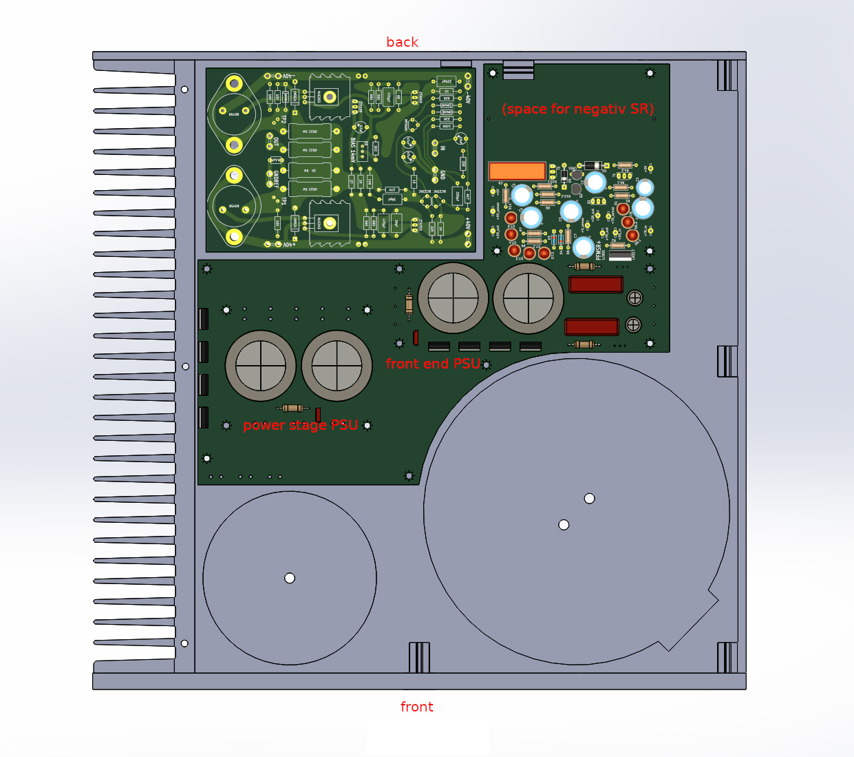
Just a comment - I think it's always better to get the rectifiers as close as possible to the transformer so it might be better to swap their position around. I appreciate that you’ve probably laid it out this way to get the output stage rectifiers on the heatsink but I’ve never found any issues with having them in free air and I’m using a 500vA 35v traffoThanks for helping, I edited the schematic in above posting and hope I got it right. Please alarm if there are still mistakes!
OK, I will make the negative version as soon as I have it all right. Already started with some basic layout (the TO220s are the rectifier diodes). The big PCB can be broken into individual circuits (hence so many mounting holes):
john.luckins
pfm Member
Thanks jpk for your kind offer which I'd love to take you up on. Will PM you later
in the week.
The value of R2 wants to be as high as you can get it to lower the filter cut off frequency. The trade off is with average volts dropped across the transistor. In this case it looks like the positive rail will draw about 25mA per channel and the negative without the super-reg will be about 15mA less. For a ZTX 653/753 with an Hfe of around 200 there will be approx 2 volts dropped in total, and about half that on the negative rail. That is enough to keep the collector capacitance down without warming up the device. You could increase the value of R2 but that depends on what voltage transformer you are using. The B4 buffer also used the 10k 10uF combo at very similar current levels to good effect. With these values you get 90% of the benefits of a cap multiplier with minimal cost downsides (transformer)
The advantage of bridging the NAP amps is the big reduction in 0v return currents. In class AB amps these currents are very non linear but their effects can be reduced by separate and multiple output stage 0v returns as implemented in the HackerNap. The downsides to bridging are the doubling of circuit complexity and the X2 increase in open and closed loop output output impedance. I think the result may be speaker load dependant and not suitable for very low z loads. It will also be very big. What speakers would you envisage driving with your bridged amp?
Doubling the no. of output devices has yielded promising results on the Avondale Amps with much less added complexity. I'm a little concerned about the extra loading on the VAS stage that results particularly as very few people fully understand let alone recalculate the values of the R-C networks that connect the NAP VAS stage to the output driver devices when changing the output driver load.
All I've got time for today I'm afraid. Maybe too much already.
John