advertisement


ALWSR Build Thread

I have a question for the electronics "experts".
I am just about to order the ALWSR parts and have found the 6.9V LM329 in 2 specifications, LM329DZ and LM329BZ.
If I understand the spec sheets correctly the LM329BZ should be better as it is less sensitive to temperature.
The LM329BZ parts are considerably more expensive, will they make any difference?

No, I don't believe they will and you could probably mitigate the effects of the worse temperature coefficient with some thermal insulation to reduce the effect of air currents on the device if you were concerned.
 
A quote from page 9 of the ALWSR manual helps....a little:


"D3 and D4 provide protection against excess differential mode voltage at the opamp inputs. They are not strictly necessary for the AD797 opamp, and can be left out for some very minor performance improvement, since the AD797 incorporates these diodes internally. This is not be the case for many other op-amps though.
It is the opinion of the author that it is best to leave the diodes in place under all circumstances. The performance degradation is slight, and the author would rather a very cheap external component fail, as opposed to degrading or destroying an expensive IC!"

There are no protection diodes at the input of the AD825 so I would use them.

John
 
In >decade of use of AD825 in this and erm, distinctly-experimental diy* SR approaches, - I've never had a problem without protection diodes

Don't worry if you don't fit them, in other words; the ALWSRs are a refined & long-tested layout - you'd know by reputation if they were required.

*yes even the step-too-far that decided it preferred to act as an excellent 2.1MHz power oscillator (a lovely nice clean sine approaching 22vrms... it survived, and so did my preamp.)
 
Thanks gents.
I did a number of internet searches to find if the chip had protection but no luck. None of the simplified schematics showed diodes in the requisite place but how simplified is simplified?
Cheers Andy.
 
Thanks gents.
I did a number of internet searches to find if the chip had protection but no luck. None of the simplified schematics showed diodes in the requisite place but how simplified is simplified?
Cheers Andy.

I'd agree with Martin, despite what I may have written many years ago, you can get away without the diodes, potentially you reduce a bit of non-linear capacitance there too, so there may be a tiny sonic benefit.

Andy.
 
https://www.dropbox.com/s/tnf0x6ipw17guoi/alwsr pos a.JPG?dl=0
https://www.dropbox.com/s/kforurhoertwcz7/alwsr pos b.JPG?dl=0
https://www.dropbox.com/s/8moez7qt1rizc81/alwsr pos c.JPG?dl=0
https://www.dropbox.com/s/cudvgnajhvhtu5u/alwsr pos d.JPG?dl=0

Pictures of +ve boards under construction. Planning to power a Naim Prefix so 24v x2. Just waiting for R8 & R9 to arrive.
Following the manual closely I managed the SMD soldering just about.
The components were a tight fit as stated in the build manual, so some are further from the board than I wanted.
Initially I mounted the ZXT751s the wrong way round but noticed in time, I still had to wreck all four removing them. I hope I have it right now.
The TO220 devices have a thick tab which is nice for heatsinking.
C_kelvins are under the board, see picture.
I used the Google sheets BOM with a pair of oscon sepc 100uf 16v per board rather than my own odd spare capacitors.

I will let you know how testing goes.
Thanks to ALW and timH
 
New to the forum and just found this thread.
I built 2 pair of jungs from boards supplied to me from someone in the Bristol area way back in 2003.
These regs are still in service and I havent bettered their performance in audio circuits with anything ive built over the years.
I recently built a DACT phono amp and would have loved to have put 4 jungs into it.
Are boards still available or am I too late ?

I do still have some boards available, you may have bought the previous boards from Patrick Dixon (at-tunes) who distributed the PCB's on my behalf for a few years.

Drop me a PM I have +ve and -ve boards available, I should have a count up to see if anyone else wants any more...

Andy.
 
Just built 4 regs, 2 +ve which work fine and 2 Neg which have a startup issue.
Im using AD797's in all 4. All components are ex RS or Farnell
To fault find the start up issue the negs are fed with pre reg out of circuit, the input voltage to SRIN, R8 and R9 1k. On switch on the output goes to 4.6v. Touching the output rail with input voltage via a 1k triggers the reg into its operational condition Output -13.5v. Reg works fine with varying loads and input V
Anyone any suggestions?
 
I really don't recommend using AD797's in these reg's, they are so prone to instability and problems, some of which won't be obvious without test equipment (e.g. high frequency oscillation beyond the bandwidth of basic oscilloscopes).

Do you have another op-amp you can try (AD825's almost never have issues)?

Startup relies on the current source that feeds the base of the pass transistor, this starts the output voltage rising, once things rise sufficiently for the op-amp to start operating, excess current is sunk via T2 under control of the op-amp to keep regulation. What diode do you have in D2? and what voltage do you measure across it, the zener is part of allowing the output to rise sufficiently to get into the operational area for the rest of the circuit.

You could make some comparisons bewtween the +ve and -ve reg's for a clue.
 
Thanks for the pointer Andrew. Ill get back with more info when Ive done more comparisons.
I used AD797 s in the last 4 I built about 10 yrs ago and no issues to date. When working the -ve reg outputs are clean, Im using a 60 MHZ Tektronix scope.
 
You are correct Andrew.
The issue is the Zener D2. My circuit shows this as a 1N4728 a 3.3v zener.
I went back and found the documentation from my original build of some 10 years ago. The info there indicates that D2 is a 1N5342 which is a 6.8 zener. I wired up two 1N4728 's in series and the neg regs switch on fine. (The old info indicates a 1N5333 3.3v zener is used on the 5v version)
Output clean no sign of any oscillation.
I read recently on the forum, in a comparison of high performance regulators, that the Jung performs at its best with the AD797. performance figures were given. Im dashed if i can find the thread but if I do Ill post a link
Many thanks for your help.
 
I am extremely frustrated: I can't get my ALWSRs to work properly. Half of my boads are flickering, see this video:
I swapped lot's of components as documentation is very unclear about resistor values and other basic information (BOM says different than stuffing guide / manual / schematics etc.)

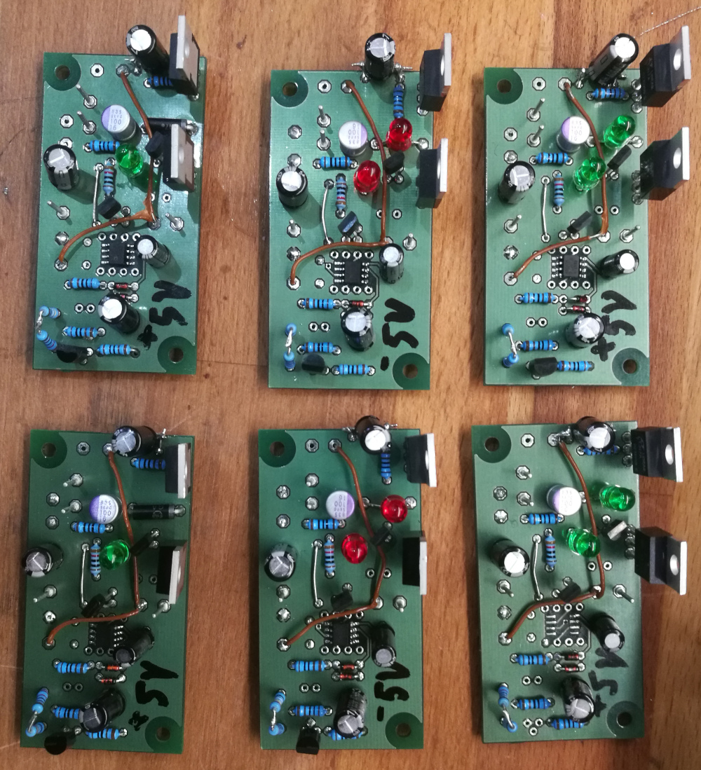
Here are the boards I built so far:
oSpJCoG.jpg

The boards with red LEDs are -5V versions, the ones with green LEDs are +5V, two of the latter have zener in place of the upper LED. The ones with 1N5333B output 4.33V instead of 5V. I replaced LM336-2.5, resistors, pre-regs, nothing helped. Even worse: 2 boards I destroyed by just replacing R7: and I couldn't get them back to work after changing back to original state. Soldering bridges etc. etc. tested countless times. It took me 2 full days of troubleshooting without result. Following information found at various places I used Pana NHG caps (22u for decoupling the opamp, the rest are 47u); MRS25 resistors, AD817 as opamp. Underside of PCB: wire links configured for local sensing. Tested with and without load. The scope doesn't show oscillation.

Other "minor" problems:
- the +5V versions output 5.1~5.2V, often at startup the voltage is even 0.2V higher and settles after 30sec
- the +5V versions with zener in place of the upper LED output 4.33V instead of 5V
- the -5V versions output -4.85 to -4.95V
- desoldering destroys platet through holes
- ground plane is prone to shorting to solderings
- hole distance is so narrow that components get a lot of heat during soldering
- stuffing guide unusable but no silk screen
- online manual nice but impossible to download / print / archive
- etc. etc. etc. etc.!!!!!!!!!!!

I spent quite some money for the 10 boards and the parts for them because I trusted the reputation of the ALWS regulators. But now I have to strongly warn against them: the boards have serious flaws, any attempt to repair them will destroy them almost certainly (in my case 100% failure rate: only the unchanged boards work stable but output wrong voltages), component values are guesswork. Even studiying all threads on diyaudio and PFM plus various versions of the so called "documentation" including the version at Acoustica will not get you there.

Big disappointment, really.
 
I’ve made loads of these boards from 24v to 15v, 5v and 3.3v. Plus and minus. I’m also about to make some +55v versions for HackerNap front ends. All have been fine and Ive modded some for different voltages by swapping out resistors etc. These are excellent products. Stick at it. Ask for help each step of the way if necessary
 
I've built at least 40 ALWSR's and they don't always work first time for me even now. I noticed that the one you show in the video has no load connected. Try it with a resistive load that will sink > 5 mA which is what the Pre reg needs to operate correctly. Also I can't see the reverse of the boards to tell if you have linked TROUT to SRIN and SRGND to 0VSENSE. See figure 7 on Page 26 of the latest manual for the details.

Don't give up. They are very much worth the trouble.

John
 
Following on.. You could just pop them in the post to me and I could set them up for you. You've done all the boring bits and I have time to kill over Christmas thanks to COVID. You do however deserve the satisfaction of a successful result. Drop me a PM/start a "Conversation" with me here if my assistance is of interest. I enjoy a little challenge.

John


advertisement


Back
Top