advertisement


ALWSR Build Thread

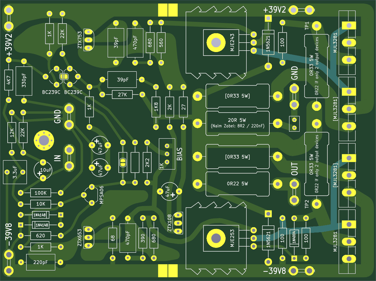
In the meantime I would STRONGLY recommend parallel output devices as here https://pinkfishmedia.net/forum/threads/hackernap-parallel-output-transistors.216188/

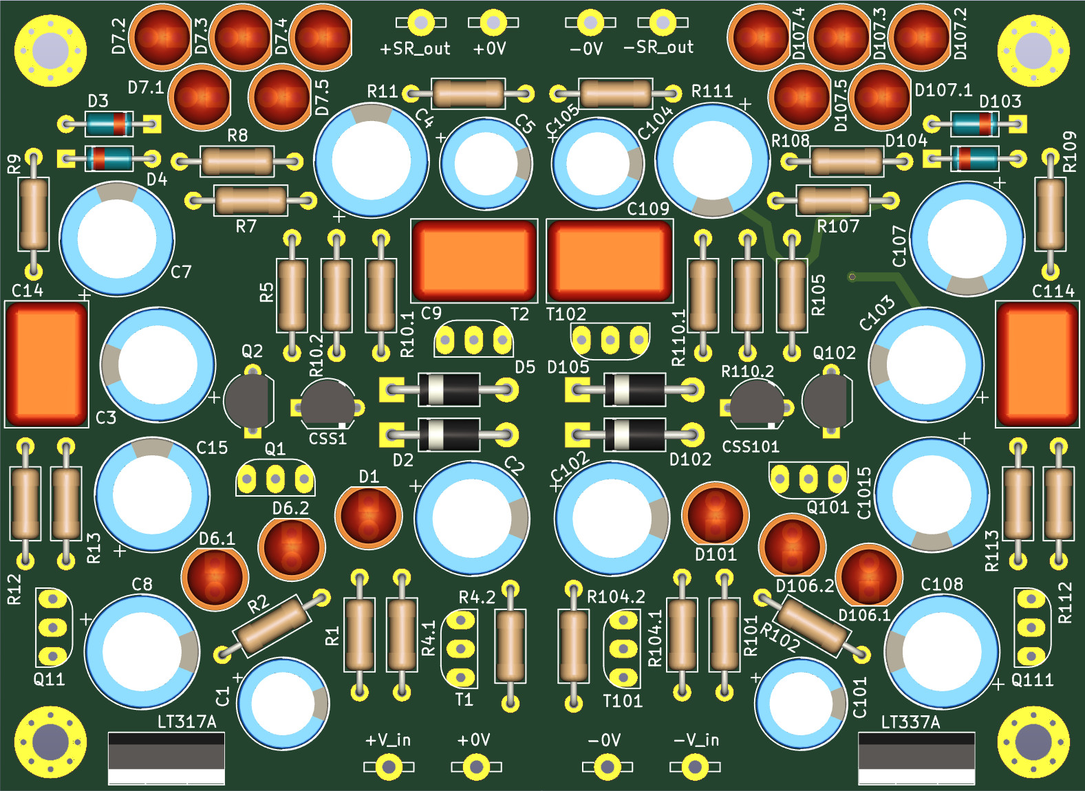
I designed a PCB for that based on Jeffs layout but never tried it. It can be populated with 2 or 4 output devices. I am not sure if I remember correctly that a forum member successfully used MJE243/253 to drive four MJL3281s. Note this circuit has the TR3 CCS mod included and if needed the 2 small jumpers in the LTP can be cut to fit emitter degeneration resistors into the empty footprints:

pCZWzXL.jpg


Just a comment - I think it's always better to get the rectifiers as close as possible to the transformer

I tried to move them around already - good news that the diodes don't need to be heat sinked! Will work on that, thanks!

What speakers would you envisage driving with your bridged amp?

Small ones such as Harbeth 30.1s or the Ergo IXs from the group buy. At that time I also tried the NAP500 on Kans and was totally surprised how much of a difference that made to them driven by two 135s, heck I even prefered them passive with one 500 to the active NBLs driven by the six pack. So I don't need the power of bridged amps, but I want the quality of the 500.

In class AB amps these currents are very non linear but their effects can be reduced by separate and multiple output stage 0v returns as implemented in the HackerNap.

I checked the schematic and build notes of the HackerNAP and found no extra 0V returns from the power section except from the supply rail caps - do you mean these...?

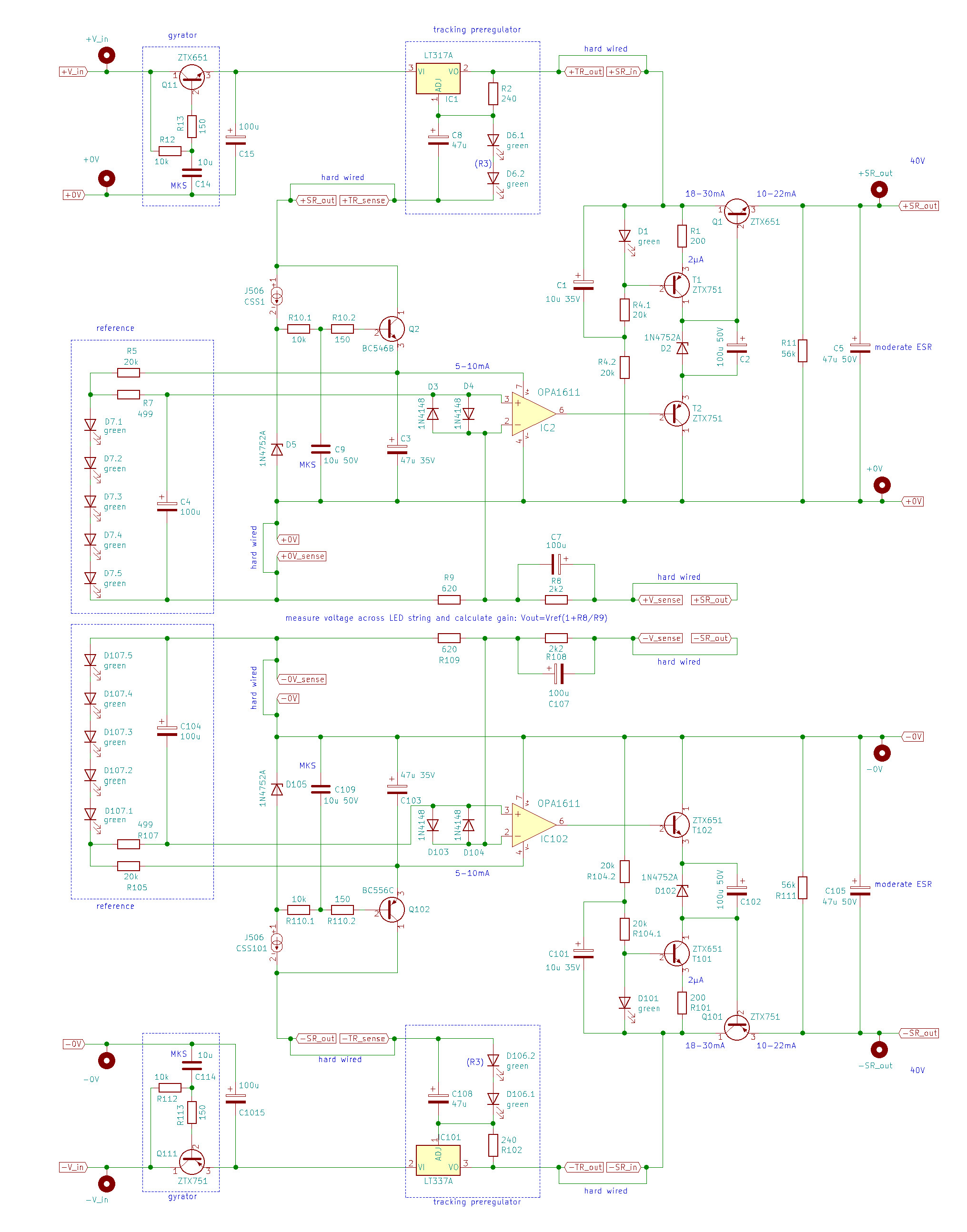
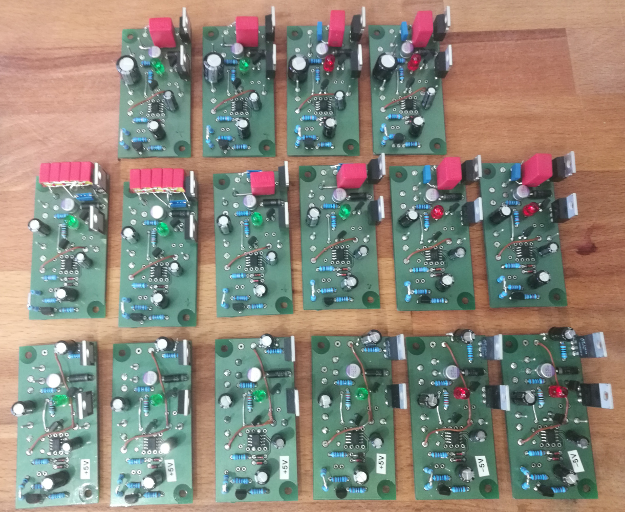
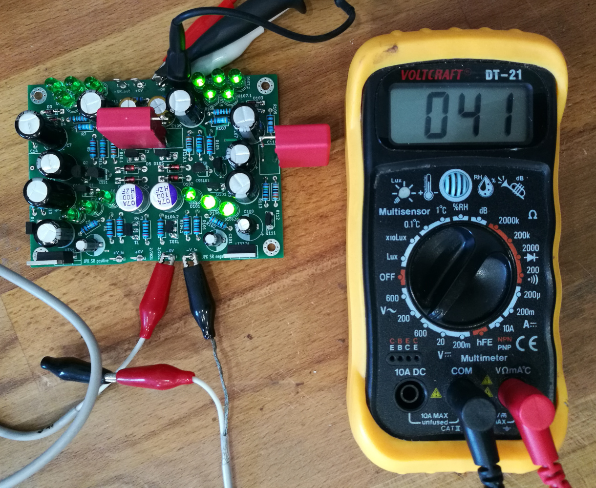
Sorry to be off topic, I am working on the super regs and will post about them as soon as I have a layout ready including the negative rail.
 
Last edited:
Here's a connection diagram from the HackerNap manual showing the ground returns

Yeah I meant that diagram. The 3 top most green lines return from the output section, 2 of these from power rail caps. As far as I can see all others are front end returns, plus one for the star point to the power stage PSU.

I have the Gerber's for the HackerNaps if you'd like to have a look

I also checked the schematic and the gerbers: the 4th and 5th green connection from the top is labelled something like "FE0V", that means front end return, and they go to the front end PSU...
 
Thanks jpk for your kind offer which I'd love to take you up on

Welcome! Here is the board, it measures 70x100mm and has both positive and negative circuits on it with cap multipliers and pre regulators:

mP1l7s3.jpg


The full schematic with part references corresponding to the ones in the original ALWSR schematic:

Y8Wkryy.jpg


It was not so easy to mirror the PCB in Kicad: first I needed to flip all parts and tracks to the other side in Pcbnew, saved the file and closed Pcbnew, edited the file with a text editor and changed the cu-layer of all tracks and parts with search/replace, opened the file again in Pcbnew and reversed all polarized parts. The schematic file I also edited with the text editor to search/replace the part references to make them read +100.

In any case I tend to overlook my dyslexic kind of mistakes, so if you spot an error please alert! Othwerwise I am ready to place an order for the boards / parts...
 
Last edited:
Hi jpk - looks good. Can you put me down for 4 of these boards please - just let me know what I owe you.
 
  • Like
Reactions: jpk
I’ve had a look at three parts of the schematic so far. The Gyrator circuit looks fine as does the pre-reg. The CSS1 circuit still specifies the J506 rather than the E-152
 
The footprint accepts both parts, the BOM will also list both. You are welcomen to PM me about the boards!

Did you complete your ALWSR 55V version???
 
Last edited:
I think it's always better to get the rectifiers as close as possible to the transformer

I tried to move them around a bit, and either they are far from the caps and near to the transformers or as I had them: far from the transformers and close to the smoothing caps. I thought the transformer is a long piece of wire anyway so it would harm less than having the charge currents travel to the caps over long distances, or is my logic rubbish...?
 
An E152 will be fine and easier to source, Mouser have some. The R10.1 and R10.2 should connect the cathode of the J506/E152 to the base of Q2.

John, I received J507s from Ebay, and they look genuine: are these OK or should I order E-152s to be shure? With 1.8mA the J507 has higher current than the J505 or J506s...
 
I tried to move them around a bit, and either they are far from the caps and near to the transformers or as I had them: far from the transformers and close to the smoothing caps. I thought the transformer is a long piece of wire anyway so it would harm less than having the charge currents travel to the caps over long distances, or is my logic rubbish...?

I'm just going on a post from Martin Clark about this but I can't find the post now :(
 
  • Like
Reactions: jpk
John, I received J507s from Ebay, and they look genuine: are these OK or should I order E-152s to be shure? With 1.8mA the J507 has higher current than the J505 or J506s...
I'd stick with the J507's, they will be fine and may even slightly reduce zener noise with their higher current though I doubt that could be measured let alone heard. The good thing is that they have plenty of volts across them.

By the way I've just been playing around with using a LT3045 regulator board as a tracking pre regulator replacing the LM317. It is a definite improvement in a sensitive circuit ( a DAC clock feed) but comes at a considerable price in terms of complexity and cost. It would be fairly easy to upgrade to it later using a small three pin daughter board.

John
 
  • Like
Reactions: jpk
I'd stick with the J507's, they will be fine and may even slightly reduce zener noise with their higher current though I doubt that could be measured let alone heard. The good thing is that they have plenty of volts across them.

Thansks for clarification!

By the way I've just been playing around with using a LT3045 regulator board as a tracking pre regulator replacing the LM317. It is a definite improvement in a sensitive circuit ( a DAC clock feed) but comes at a considerable price in terms of complexity and cost. It would be fairly easy to upgrade to it later using a small three pin daughter board.

There are some adapter boards on Aliexpress and Ebay, and also this one. If these would make it necessary to adapt the periphery on the super reg board I would like to adapt my layout accordingly.
 
Thansks for clarification!


There are some adapter boards on Aliexpress and Ebay, and also this one. If these would make it necessary to adapt the periphery on the super reg board I would like to adapt my layout accordingly.

That is the same seller that mine came from. My only concern was the 10uF input capacitor that will in effect be connecting directly to the regulator output. It is needed for input stability but I did wonder if it would be better off being connected to 0v. In practice I have tried this a few times now and ended up keeping it in place of the LM317. There is a negative version, the LT3094, and that seller used to have them as well for a LM337 pre reg replacement.

John
 
  • Like
Reactions: jpk
I managed to populate all PCBs and got them working finally:

WuixXKZ.jpg


Some of them have VBE instead of the tracking pre regulator as described here:

9i7cgv1.jpg


One thing which made a lot of troubles was flux near the opamps: I did never expect that even faint remainings of flux actually can conduct enough current to make the hole circuit fail.

Thanks for the help and apologize for being so negative about them earlier!
 
Assembled and tested the high voltage version (for NAP fron end) today:

qjvGpgP.jpg


Works well, the big red films will be replaced with small footprint MKS, the rest is fine. Thanks John and Tim for great help!!
Oooooh..very nice.

Would it be possible to purchase a few PCBs from you please? I'm thinking of the front end for my KSA50 Clone and maybe the FE for the Stasis amp I'm building...


advertisement


Back
Top