advertisement


Replacing the ALWSR's pre-regulator by a VBE

For very small systems (PFM Flea type problems) a JFET would be a lovely choice, as the inter-electrode capacitances are smaller than comparable MOSFETs, and JFETs have much lower noise. This would only work up to about 10mA or so, depending on the device chosen (2sk117 is good for 10mA).
 
PigletsDad said:
If you want lower output impedance you need to use a bipolar, or a more complex circuit with more active devices.

Or put a 100 to 470 microfarad cap from source to ground.
 
PigletsDad said:
For very small systems (PFM Flea type problems) a JFET would be a lovely choice, as the inter-electrode capacitances are smaller than comparable MOSFETs, and JFETs have much lower noise. This would only work up to about 10mA or so, depending on the device chosen (2sk117 is good for 10mA).

Unfortunately the output impedance with even a high Gm jfet like the 2SK170 will be in the several 10's of ohms and starting to be too high of an output impedance for a preregulator.
 
FDIECK said:
Or put a 100 to 470 microfarad cap from source to ground.

For example, an ultra-low ESR electrolytic such as a 100uF/35V Rubycon ZA...? It just so happens that I use these very caps at the input of the SRs, which is directly connected to the source of the irf610...

They use to be 47u Elna Silmic 2s, but I swap them for lower ESR devices.
 
FDIECK said:
Unfortunately the output impedance with even a high Gm jfet like the 2SK170 will be in the several 10's of ohms and starting to be too high of an output impedance for a preregulator.

Sure, you would have to design the low current main regulator specifically round such a limitation.
 
Having found improvements (to my ears) by switching from an IRF610 to an IRF520 on my gyrator I noticing that the principle difference between the two was the higher Gm of the 510. Gm in these devices tends to increase with drain current, as well as becoming more linear with Vgs variations. So I put a couple of heatsinks on the FET's and started loading the source of the FET to earth with 470 ohm resistors. The result is a noticable improvement in the bottom end and mid, with both becomeing more natural. The output impedance has reduced and the improvements are similar to those wrought by using better quality and oversized transformers.

I could take this further, with greater load resistors and more FET's in parallel if worthwhile. I suspect the capacitor on the FET's output could have a significant sonic impact as well, and will try reducing its value and improving its quality in due course. I'll try and take some current measurements at the weekend to see where the devices sit on the data sheets Gm graph. I suspect I'll need as much as an Amp to reap all the rewards this can give, but this will be at the cost of as much as 40W of wasted heat generation. The load could be switched out of circuit when not listening, and this would also allow A/B comparisons.

Too much to do. Shame I have a day job!

John
 
Over the last couple of days, I rebuilt the PSU for my cd3.5 (I'll start a seperate thread), but the salient point here is the fet-based vbe that I built for the analog stage.

The cd3.5 is pretty maxed out and has 2 ALWSRs powering the analog stage (opa627 op amps) @ 18.4V. Until now, the SRs were standard lm1086 pre-reg affairs. The PSU had a seperate 25-0-25 twin-secondary IE core trafo / mbr20200ct rectifiers / 10000 kendeil, lm1086 pre-pre-reg @ 26V. This was fed into the cd3.5 and thereby into the SRs.

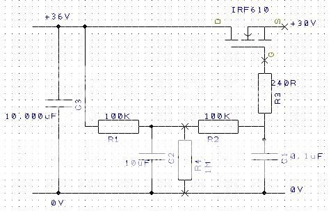
Now I've changed it... the PSU's analog rails are the same 25-0-25 trafo/rectifiers/kendeils but then I've got this little arrangement:

cdp-fet.jpg


C3 is the smoothing Kendeil
C2 is a 10uF Wima MKS4-LN metallised polyester film cap
C1 is a .1uF generic metallised polyester film cap (anyone got some .1uF polystyrenes or polypropylenes...? I'm after 6 in total)

Input voltage to the circuit is around 36V and output is 30V. It's carefully laid out on circuit board and hooked up with heavy guage silver/ptfe cabling inside the psu. Inside the cd3.5, I've removed the lm1086s from the SRs and bypassed the prereg section completely, but this means I'm dropping around 12V on the D44H8 on the SR and it got pretty hot! To counter that, I drilled the floor of the player and bolted the SRs directly to the chassis via sil-pads. That keeps them cool :)

Now, the sound... bearing in mind that part of the PSU rebuild added an extra trafo winding dedicated to powering the DAC (via another on-board flea... the cdp now has the standard naim trafo for digital, the IE core for analog, and a dual-secondary 0-18V for the clock [also via a flea] and the DAC) then this rearrangement of the analog PSU filtering is awesomely good.

Again, it's the basslines that get the real benefits... absolutely rock-solid, unwavering, fast deep notes that attack and decay with amazing precision. It makes the previous PSU sound positively wooly! Another benefit is in complex musical passages that I've never been entirely happy with before, where instruments could be seperated but somehow mushed together and lost coherence; now the soundstage remains open and the instruments remain distinct and voices maintain their presence.

In short, it's a wonderful upgrade and, thanks to PD and FDIECK, the IRF610s have remained nice and stable - no problems with oscillation now :) I'm going to use this setup for the SRs inside my 62 now...

Happy hacker :D

Ok, time to try the Mosfets infront of my Arcams +/- regulation.
I've got the IRF520NPBF N-ch and IRF9520NPBF P-ch. can I use the above circuit for both of these Mosfets? one using positive voltage for the 520 and the second one for negative using 9520?
 
Hi all,

In the last entries, the FET model always appears to be more advantages than the BJT/Darlington model. The fact that the BJT/Darlington circuit has an advantage which the FET circuit does not have has not yet been touched upon: I can put more SRs on one transformer. How can I do this with an FET circuit?

Ronald
 
Ronald,

The IRF610/520 FETs are drop-in replacements for BJT power transistors such as the BDX33C etc, provided you add the 240R stopper resistor. As long as you can handle the extra voltage drop that you get with a FET (approx 4V), I can't see why it would make any difference and you should be able to run just as many SRs from one transformer.

Anyone else care to chime in with an answer on this one?

Carl
 
I agree with Carl.

Provided you can live with the bigger voltage drop, you should be able to run lots of SRs off a single transformer.

Because the output impedance of a FET pre-regulator is not that low, I don't think it would be a good plan to use one FET, then split to several SRs. Instead, I think each SR should have its own FET - but as the devices are cheap (less than a pound), this is not a very expensive approach.

Although the output impedance of the FET is only moderate, the cross-impedance of this approach is excellent - current drain on one SR will cause hardly any voltage change at the output of the FET on another branch.
 
Thank you for the answers. I did not formulate my question accurate. I try it differently.

I wanted to exchange only in the circuit of Teddy_Pardo

vbe.jpg


the 'normal' transistors with MOSFETs. So that I can use the advantages of both solutions fully. Because I want to operate like teddy several VBE-SRs at one Transformer.
 
Herat - you can still do that with FETs.

My motivation with the above circuit was to share one filter (the capacitor I used are large expensive, and hrd to get, so I couldn't afford many of them). You can still have a common filter for many FETs, all you need to do is ignore the 547 and connect all gates to the same filter.
 
Teddy is right.

The only other thing to point out is that each FET must have its own gate stopper resistor. Hacker uses 240 Ohms, but I expect you could get away with lower values like 100 Ohms.

You also have the option of increasing the values of the resistors from 30K to say 330K, to get more rolloff, as the FETs need almost no bias current. This circuit would take a longer time (20 seconds) to stabilise, but would have better than 100dB ripple rejection at 50Hz in the filter.

Another option is to use smaller, and hence cheaper, capacitors with the higher value reistors. For example, you could use 1uF caps with 330K (or whatever value) reisistors.

Finally, if you are doing a new build, rather than modifying any existing one, I suspect there is some advantage in using a smaller cap as the second one near the transistors in the FET case, as the RF resonance on the cap will be at a higher frequency, helping to get good RF rejection.

If using BJTs you absolutely do not want to use a small cap for the second cap, as they finite current gain, the low frequency output impedance will be worse.
 
If using BJTs you absolutely do not want to use a small cap for the second cap, as they finite current gain, the low frequency output impedance will be worse.

PD - Can you elaborate on that? My understanding is that the output impedance is determined by the resistor and the transistor's hfe. How is the capacitor influencing the output impedance?
 
Terry,

For simplicity, lets just think about a single pole circuit; the output impedance of a two pole turns out to be much the same, but the argument is simpler.

For a BJT the output impedance is the sum of two terms. The first is the inverse of the transistor transconductance - this is 26/I Ohms were I is the current in mA.

The second is the impedance seen at the base, divided by hfe. The base sees the bias resistor in parallel with the final cap (roughly, but close enough). At very low frequencies, the output impedance is the resistance divided by hfe, but as frequency rises, the resistor gets shunted by the cap, and the output impedance falls.

This is why this circuit is sometimes called a "capacitance multiplier" - over a certain range of frequencies it gives an output impedance much like what you would expect from the capacitor multiplied by hfe.

FETs draw almost no gate current, and so the output impedance is resistive, frequency independent and somewhat higher (say a factor of 5) than you get from a BJT operating at the same current.
 
Hi all,

I pursue this threat for a long time with large interest.

I considered myself a variant for the FET VBE. I believe that it is better, if each VBE has its own condenser. The advantage: The condenser is close at the FET. So the circuit could look. Could that bring advantages?

FET-VBE_V2.jpg


R1 = 100K - 330K
R2 = 100K - 330K
R3 = 100R - 240R
C1 = 10uF
C2 = 1uF
FET = IRF610


Kind regards, Peter
 
Peter,

That looks like a good circuit, which will give lots of isolation between branches, but not need too many big caps.


Julian


advertisement


Back
Top