advertisement


Replacing the ALWSR's pre-regulator by a VBE

Hello Im a new forum member.
This is a very interesting thread! But I haven't figured out some of the pieces yet.
I want to build a +- 15V regulator using ALWSR (or peranders JSR03/05 as i live in sweden) with VBE as pre-regulator.
To use with a active filter for Linkwitz Orion speakers.

Is it possible and how would you do it?

Does ALWSR support negative voltages and what to use instead of instead of IRF640 in the negative section.

regards Joel
 
Hello everybody,
Wen I read this thread, I see a (good) filter is importend, So I ask myself, and you, is it possible to implement a noch filter, adjusted on the rectified voltage (100 Hz)?
regards
Woood09
 
This would be a very good idea.... if.... we were working with sinus signals but your signal is sawtooth shaped which will result in harmonics, 100, 200, 300, 400 etc Hz. It's not only one frequency. Besides, a super regulator has an extremely good power supply ripple rejection => hardly necessary.
 
Hi anybody
I have build a vbe multiplier, schematic post 247 of this thread,
and be very happy with it. I use the vbe in the shiga clone.
To anybody thanks a lot.
Best regards
Woood09
 
Hello, I am new to this forum and very interested in that circuit, I like to use for a N.P clone preamplifier.
Does anybody have pcb´s to sell to germany, or has a Target file, w/o the VBE.
Does anybody has proper values for +/- 60 V output?
Thanks for any help
Michael
 
I never did try this VBE mod on my ALWSRs, but a group on people in this excellent thread achieving some good results by by-passing the ALWSR's pre-reg with a VBE cct.

I thought some people new to ALWSRs would appreciate reading some of the testing, explanations and work in this thread. There are even some simple ccts from about post 201 onwards.

PS. I'd like to figure out the -ive implementation of this cct for -ive ALWSRs.
 
Last edited:
Over at diyaudio.com jackinnj did some measurements with and without the pre-regulator and the result was a bit increased output impedance when using the pre-regulator. At the moment I can't find any reference for my statements.
 
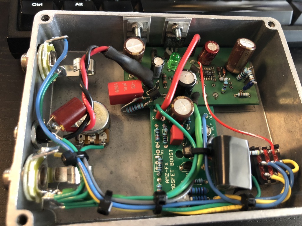
I've used a simple VBE + pre-reg with great success in a super clean boost guitar pedal (yes, it's overkill but hey it was all cobbled together with parts from the bits box).

The VBE is installed before the ALWSR's prereg so the order goes: raw supply -> VBE -> prereg -> ALWSR -> circuit being powered. I'm not using the ALWSR's remote sensing. I've added a 330uF Panasonic NHG cap at C1 on the ALWSR (it decouples the output of the pre-reg and input of the alwsr) instead of the standard 47uF. I've also added a 47uF cap across the input of the VBE because the raw supply is several feet away and I want to keep the pre-reg LM1086 happy/stable:

The VBE is just 2k2 / 10uF Wima MKS2XL / BC547C, and I'm going to experiment increasing the 2k2 as much a possible until I reach the maximum voltage drop that this circuit will tolerate (slow startup isn't an issue here):

rDX98ol.jpg
 
Oh, fun!

Carl, increasing the series R increase the output impedance and that means, on the input, a '317/337 will get unhappy at some point *.
I've long suggested - for BJT pass devices - to keep the VBE R value low, 1-2K2 or so in a case like this, and increase the cap instead; go electrolytic if need be, there's no penalty here. 1000R/47-100uF is a good brickwall.


* as an upstream filter to these and other generic 3pin regs, keeping input impedance under 10ohms wideband works for me. Preferably a single-digit number. It also helps the output side performance, if the 3-pin thingummy is your primary regulator.


advertisement


Back
Top