advertisement


Replacing the ALWSR's pre-regulator by a VBE

No free samples .........

Ah well, I will try another route.

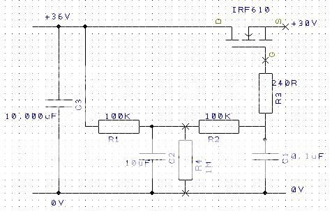
By the well the circuit that is evolving here is rather similar to the classice Pass Labs Aleph P1.7 preamplifier. It uses the IRF610 (a favourite of Mr Pass I believe) but relies on a zener stack to provide regulation as it does not have a downstream regulator.

It has a 221 ohm gate resistor very close to the Fet to prevent oscillations.
 
Hi Guys,

I've been missing out on this thread so decided to give the normal VBE a go in my modified Arcam A5 using TIP132/137 Darlingtons.
Here is before and after schematic of the Arcams regulator section, not had chance to listen to it yet so if I've done anything wrong please let me know:) theres a couple of volts drop after the Darlingtons which is fine
http://pic20.picturetrail.com/VOL1293/4634025/9699445/181548200.jpg
http://pic20.picturetrail.com/VOL1293/4634025/9699445/181548196.jpg

Sorry the image isn't very good, how do you post PDF's on here?
 
I've been listening to the VBE mod for a couple of days now, it certainly seems to have potential:)
Anyone with an Arcam Alpha5/5+ will notice this can easily be implemented on the Audioboard.
182598449.jpg

I now have changed the resistor to 20k and the cap to 2 x 3.3uf in parallel, their legs have been cut short, the cap on the emitter is 10uf tants, I'll try some different caps later.
I'm still currently using Tip132/137 Darlingtons for the +/-V supply. I'd like to also try Fets next just to see how much they change the sound, I do have a pair of IRF610's but what is suitable for the negative supply?
 
ron - if you have enough voltage overhead, do try a gyrator ahead of the -15v reg for your TDA1541's supply (eg 10K/3.3uF) Give it at least 24hrs to settle and let me know what you think...
 
martin clark said:
ron - if you have enough voltage overhead, do try a gyrator ahead of the -15v reg for your TDA1541's supply (eg 10K/3.3uF) Give it at least 24hrs to settle and let me know what you think...

No problem Martin, I'll do it tonight if possible and let you know.
I presume just like whats done in the flea? problem is the adjustable -15v reg also supply the negative rail of the I/V and output filter section plus the -5v adjustable reg for the digital part of the dac so those regs see a fair bit of current.
Theres about +/-26v measured feeding the audioboard, what transistor would you recommend?
I'd post the Arcams schematic for the audioboard on here if I could
 
Ooh that's a shame. I'd suggest you give the dac it's own -15v, +5v, -5v regs at the very least...

Supply output impedance doesn't seem to matter much for the -5v feed to a TDA1541 but definitely does to the -5v and +5V. The latter is critical - the output current from the dac is mirrored here, inverted ;) Yes - I do mean the dac's output also appears, summed, on the +5 pin...
 
martin clark said:
Ooh that's a shame. I'd suggest you give the dac it's own -15v, +5v, -5v regs at the very least...

Supply output impedance doesn't seem to matter much for the -5v feed to a TDA1541 but definitely does to the -5v and +5V. The latter is critical - the output current from the dac is mirrored here, inverted ;) Yes - I do mean the dac's output also appears, summed, on the +5 pin...

Cheers Martin, I actually went mad on my older Arcam and gave everything its own ALW SR, my latest A5 is screeming for some more work here:D

Hmm, so something like an Oscon may come in useful ;)
 
martin clark said:
Very useful. esp if you use a 47uF oscon after, say , an LM317/337 with maybe 0.33R btween it and the reg. ;)

I was thinking across the dac pins:D
Arcam was very tight with the regs:( my board is mainly filled with ZL's, I liked the sound of these better than the ZA's in this cdp
 
ron said:
I'm still currently using Tip132/137 Darlingtons for the +/-V supply. I'd like to also try Fets next just to see how much they change the sound, I do have a pair of IRF610's but what is suitable for the negative supply?

I'ts the IRF9610 P channel MOSFET. there are no complementary MOSFET's like in BJT's, but 9610 if very close to the 610.

Avi
 
hacker said:
Over the last couple of days, I rebuilt the PSU for my cd3.5...
... Until now, the SRs were standard lm1086 pre-reg affairs. The PSU had a seperate 25-0-25 twin-secondary IE core trafo / mbr20200ct rectifiers / 10000 kendeil, lm1086 pre-pre-reg @ 26V. This was fed into the cd3.5 and thereby into the SRs.

Now I've changed it... the PSU's analog rails are the same 25-0-25 trafo/rectifiers/kendeils but then I've got this little arrangement:

cdp-fet.jpg


C3 is the smoothing Kendeil
C2 is a 10uF Wima MKS4-LN metallised polyester film cap
C1 is a .1uF generic metallised polyester film cap (anyone got some .1uF polystyrenes or polypropylenes...? I'm after 6 in total)

Input voltage to the circuit is around 36V and output is 30V......Inside the cd3.5, I've removed the lm1086s from the SRs and bypassed the prereg section completely :D

Carl,

I did the same configuration with the VBE + S-R, it was the best VBE I have heard, but after a few days, I have got a nasty oscilations from my Super-reg.
connecting the LM1086 pre-reg stoped the oscliations completely.

Can you double check eveything is O.K with you'r bare S-R (without the 1086)?

Avi
 
I just knocked up three separate gyrator regs for the dacs supply in my Arcam, thanks to Martin Clark for suggesting this one:cool:
Now the modded VBE'd onboard regs supply the I/V and output section only
184006410.jpg

184006417.jpg
 
martin clark said:
Ooh that's a shame. I'd suggest you give the dac it's own -15v, +5v, -5v regs at the very least...

Supply output impedance doesn't seem to matter much for the -5v feed to a TDA1541 but definitely does to the -5v and +5V. The latter is critical - the output current from the dac is mirrored here, inverted ;) Yes - I do mean the dac's output also appears, summed, on the +5 pin...

It goes back into the -15, not agnd..
And current ref generator supply is between -15 and -5..

hihi
 
Hi all,

I've experimented with two different types of FET for the gyrator and come to an interesting conclusion. I compared the IRF610 with IRF 520, with a week of each in a circuit very similar to that drawn by Hacker above. I have R1 and R2 =47k, C2 as 20u and C1 = 470nF Polystyrene (very big). I have gate stopper resistors as well.

The IRF 520s comprehensively outperform the IRF 610's, even though the latter are a faster lower capacitance device. The IRF 520's have one significant advantage. They have a higher gfs, and therefore a lower on resistance. Drawing up the equivalent circuit shows the stability and high value of gfs to be the most important element of the FET gyrator. The IRF 520 has a gfs that is 3-4 times higher than the 610 at 4 S. Output impedance is roughly the inverse of this at approx 0.25 ohms, but only at high currents. I'm now trying to maximise the gfs of the FET either by finding a better device or by biasing it better. The standard idling current of a naim pre amp is not realy sufficiant to get the IRF 520 into the area where its gfs is greatest of most stable with Vds variations. I'm planning on loading the FET output up with high wattage resistors to draw more current and then heatsinking the FET properly. Things are going to get warm, but I expect a further reduction in output impedance to be audible. Parallelling up the FETS as well as pulling more current through them will help further.

Anyone know of a FET with a higher gfs than the IRF 520's?

I found the IRF 610 reduced the depth of the bass, reduced the channel seperation and made the sound field very small. IRF 520 opened thing out a lot and the bass tightened and deepened. I hope there is more of this improvement to be had.


Anyone know any better FET's than IRF 520's for gfs?

Cheers

John
 
Thanks Dan,

I took a look at the IRF540 but noticed that it only gives such a low rds at very high currents circa 33Amps! Looks very similar to the 520 at low currents. What is really needed is a FET with a similar low rds (high gfs) when passing 100ma. Time to hunt through the data sheets.

John
 
Sparts155 said:
Hi John, The IRF540 should be better: Rds=0.077 ohms compared to ~0.200 ohms for the IRF520.

Dan
Guys, _when_ is Rdson important? NOT in linear applications such as this. ONLY in switching applications.
 
A reasonable model gm for a FET is to say it goes something like Id x 5millimho, where Id is in millamps, up to some saturation level. Unless you have a tiny fet, pretty much anything will give the same gm at 100mA (round about 500millimho). This will give an output impedance of a couple of ohms.

Rds on is totally irrelevant.

gm at currents that are not used is also totally irrelevant.

If you want lower output impedance you need to use a bipolar, or a more complex circuit with more active devices.

But as we are talking about a pre-regulator, output impedance is not very relevant, provided it is low enough to allow the main regulator to work correctly. 2Ohms broadband is just fine for that.
 
But as we are talking about a pre-regulator, output impedance is not very relevant, provided it is low enough to allow the main regulator to work correctly. 2Ohms broadband is just fine for that.

You could even use something like a Supertex DN2540 with a 1K gate resistor for lower drain to source capacitance and better high frequency rejection than a high transconductance mosfet. This part is designed for current sources but still has a pretty high forward transcondutance. It has high drain to source output impedance for better broadband rejection of noise at its input which is really what one wants a preregulator to do well.

Per-A glad to see you back from vacation to resume fishing for regulator design information. Don't you have like a dozen different designs for sale all ready though? I will name my shunt regulator after you. The Parallel Extreme Regulator-rev A


advertisement


Back
Top