
teddy_pardo
Trade: Teddy Pardo
The following mod consists of replacing the ALWSR's pre-regulator by a capacitor multiplier.
A capacitor multiplier AKA VBE multiplier, or Gyrator, is a technique to create a virtual large capacitor from a small capacitor and a transistor. Basically the capacitance of a small capacitor is multiplied by the transistor’s hfe (for more info read here and here).
Why?
The supper regulator does an excellent job in providing low noise low impedance supply. However, as a feedback based design its performance at very high frequencies is somewhat limited (it’s still much better than monolithic regulators though). The ripple after the rectifier and even a 22,000uF capacitor has a saw tooth form of about 70mV at load, which is equivalent to a composition of high frequencies, and thus very challenging for a feedback loop regulator. I have done tests with larger capacitors and CLCLC filters and found that if I can reduce the ripple at the ALWSR input, and especially if I can give it a more sinus like form the performance of the ALWSR improves dramatically. The ALWSR’s on-board pre-regulator works basically the same way as the ALWSR (Jung) regulator itself but is even worse WRT high frequencies. Replacing the pre-regulator by a VBE multiplier gives the best of both words: the VBE creates a very low and smooth ripple (less than one mV) supply, while the ALWSR stabilizes it to the required voltage and provides very low impedance. There is an additional advantage, since the VBE is just a virtual capacitor, it doesn’t require a huge transformer to charge it, in fact I achieved very good (even excellent) results powering my NAC102 with very small transformers in the range of 10-50VA.
Another advantage is that there is no need to have many raw supply channels, many ALWSRs can be connected in parallel to a single channel supply.
And one more: The ALWSR can now be used at lower dropouts (down to around 3.5V). Note however that since most of the dropout is now on the D44H11 it may require a heatsink. (As an alternative the input voltage can be reduced by adding a resistor in parallel to the capacitor, dividing the input voltage).
How?
Fortunately, it is very easy to do it with the ALWSR PCB. In fact it can accommodate the VBE without any change to the PCB itself. Here is how to do it for a positive ALWSR:
1. Replace the 317/1086 by an NPN Darlington power transistor (I have used BDX33C)
2. Replace R3 with a 470-1000uF capacitor (it may be worthwhile to add a 1-2uF film capacitor in parallel).
3. Ignore C8
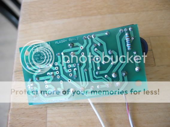
4. Replace R2 with 1K. I mounted it at the back side of the PCB to leave space for the capacitor.
5. Link TRS2 to TRGND
6. Link TRIN to SRIN
7. Use TROUT as the Input (instead of TRIN)
That’s all…
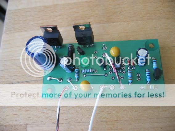
You can see how it looks in the following pictures:
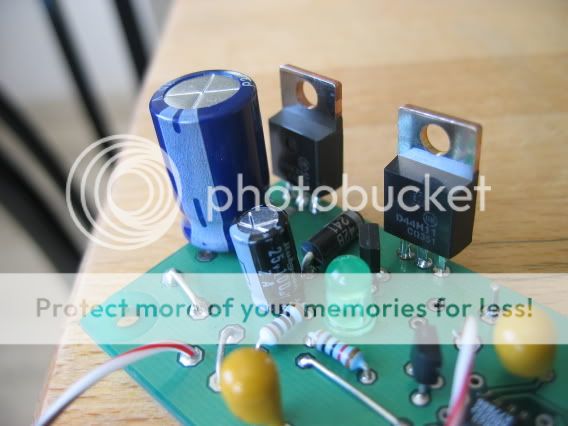
A closer viwe:
And R2 at the back of the PCB
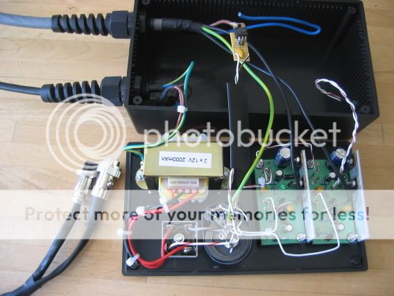
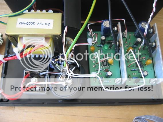
I than took it one step further and created a compact HiCap replacement for a friend in which I replaced the dual transformer by a simple 2x15V 50VA transformer, and the two 22,000uF capacitors by another VBE. I used this circuit (fig 3), in which I used only the +V part, and a single BDX33C darlington transistor instead of the two transistors.
I also used the same transformer to power the control circuits of the NAC102 (replacing the NAPSC), more on that later.
Here are some pictures of the full PSU:
and
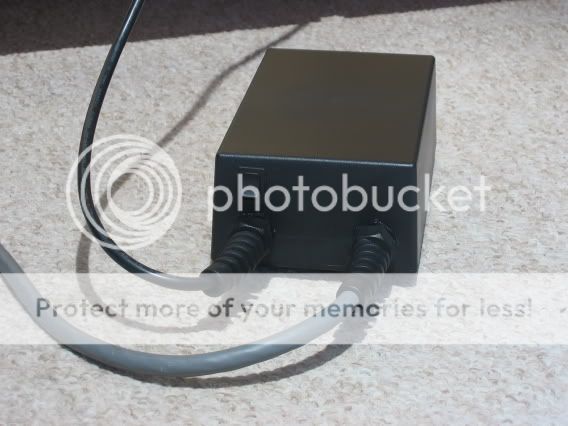
Finished:

and from the back:
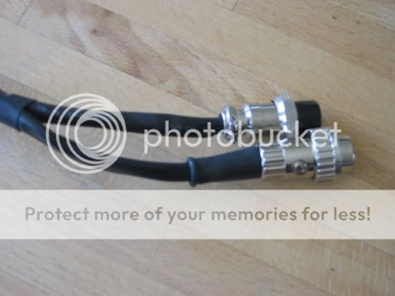
The bonus NAPSC connector:
Oh, and I forgot to say, the improvement in the sound is relly great, but who cares...")
Now seriously, it's the best thing I've listened to!
Note for NAC102 owners:
In the pictures above you can see that I used a small 317 based circuit to supply the control circuits of the 102. I then used a much better approach. Since my transformer is a center tapped 2x15 providing 41V DC, I just added a 2200uF capacitor between the ground and the center tap to get 20V DC. Simple and effective…
Unlike the HiCap, there is no issue here (at least not to my ears) with sharing the same transformer between the audio and control supplies.
Enjoy, Teddy
A capacitor multiplier AKA VBE multiplier, or Gyrator, is a technique to create a virtual large capacitor from a small capacitor and a transistor. Basically the capacitance of a small capacitor is multiplied by the transistor’s hfe (for more info read here and here).
Why?
The supper regulator does an excellent job in providing low noise low impedance supply. However, as a feedback based design its performance at very high frequencies is somewhat limited (it’s still much better than monolithic regulators though). The ripple after the rectifier and even a 22,000uF capacitor has a saw tooth form of about 70mV at load, which is equivalent to a composition of high frequencies, and thus very challenging for a feedback loop regulator. I have done tests with larger capacitors and CLCLC filters and found that if I can reduce the ripple at the ALWSR input, and especially if I can give it a more sinus like form the performance of the ALWSR improves dramatically. The ALWSR’s on-board pre-regulator works basically the same way as the ALWSR (Jung) regulator itself but is even worse WRT high frequencies. Replacing the pre-regulator by a VBE multiplier gives the best of both words: the VBE creates a very low and smooth ripple (less than one mV) supply, while the ALWSR stabilizes it to the required voltage and provides very low impedance. There is an additional advantage, since the VBE is just a virtual capacitor, it doesn’t require a huge transformer to charge it, in fact I achieved very good (even excellent) results powering my NAC102 with very small transformers in the range of 10-50VA.
Another advantage is that there is no need to have many raw supply channels, many ALWSRs can be connected in parallel to a single channel supply.
And one more: The ALWSR can now be used at lower dropouts (down to around 3.5V). Note however that since most of the dropout is now on the D44H11 it may require a heatsink. (As an alternative the input voltage can be reduced by adding a resistor in parallel to the capacitor, dividing the input voltage).
How?
Fortunately, it is very easy to do it with the ALWSR PCB. In fact it can accommodate the VBE without any change to the PCB itself. Here is how to do it for a positive ALWSR:
1. Replace the 317/1086 by an NPN Darlington power transistor (I have used BDX33C)
2. Replace R3 with a 470-1000uF capacitor (it may be worthwhile to add a 1-2uF film capacitor in parallel).
3. Ignore C8
4. Replace R2 with 1K. I mounted it at the back side of the PCB to leave space for the capacitor.
5. Link TRS2 to TRGND
6. Link TRIN to SRIN
7. Use TROUT as the Input (instead of TRIN)
That’s all…
You can see how it looks in the following pictures:
A closer viwe:
And R2 at the back of the PCB
I than took it one step further and created a compact HiCap replacement for a friend in which I replaced the dual transformer by a simple 2x15V 50VA transformer, and the two 22,000uF capacitors by another VBE. I used this circuit (fig 3), in which I used only the +V part, and a single BDX33C darlington transistor instead of the two transistors.
I also used the same transformer to power the control circuits of the NAC102 (replacing the NAPSC), more on that later.
Here are some pictures of the full PSU:
and
Finished:
and from the back:
The bonus NAPSC connector:
Oh, and I forgot to say, the improvement in the sound is relly great, but who cares...
Now seriously, it's the best thing I've listened to!
Note for NAC102 owners:
In the pictures above you can see that I used a small 317 based circuit to supply the control circuits of the 102. I then used a much better approach. Since my transformer is a center tapped 2x15 providing 41V DC, I just added a 2200uF capacitor between the ground and the center tap to get 20V DC. Simple and effective…
Unlike the HiCap, there is no issue here (at least not to my ears) with sharing the same transformer between the audio and control supplies.
Enjoy, Teddy