advertisement


Replacing the ALWSR's pre-regulator by a VBE

I have finally gotten around to doing this and the results are fantastic :D :D (note two big smilies!)

The 4 SR's inside the pre 92R have had the pre-reg's bypassed, the circuitry has been left in place on the reg boards.

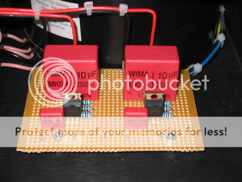
I've used Carl's circuit based on the IRF610 fet however I've changed the 1M resistor to 2M to reduce the voltage drop as my SR's are built for 28V and I it's easier to change the VBE's than the SR's.

Here's shot of my VBE's boards (two gyrators per board).

102_0297.jpg


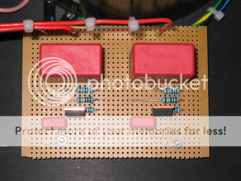
Here's a shot from above

102_0298.jpg


and here are both boards inside the PSU before I wired up the VBE's to the sockets.

102_0295.jpg


The result so far with only 30mins listening is Better than when I first used an external PSU on my naked pre - really it is that good! Looking forward to using these VBE elsewhere but without the huge film caps as they are expensive and it'll be difficult to find room for lots of them inside a pre-amp.

Thanks - well done - happy bunny here :)

Nick
 
Looks good, you've done your usual high standard of work there :) And doesn't it sound soooo much better than a standard SR?
 
Nick,

I think that you can achieve almost if not the same results, with a single (smaller) transformer, a full-bridge rectifier, a single 5,000-10,000uF capacitor (even a small low-cost one), and even a single set of filter capacitors driving four transistors.

Teddy
 
Can I ask where you bought the Wima 10uF MKS caps from please?

Barry, these were samples ordered by my business direct from Wima.

Follow this link - if your not too greedy you will find them very helpful :)

Carl - indeed - this change has realy brought my pre out of its shell - it seems to be the mod that the system has been waiting for as I've lots of doubts about my PA and speakers recently - these have now totally disappeared.

The result is a more engaging and involving sound at every level - the bass in particular has more presence which is nice :)

think that you can achieve almost if not the same results, with a single (smaller) transformer, a full-bridge rectifier, a single 5,000-10,000uF capacitor (even a small low-cost one), and even a single set of filter capacitors driving four transistors.

Teddy, I'd noted your report on this before. I am reluctant to ditch the big trafo/ big cap box just yet - just can't bring myself around to that way of thinking just yet :)

I do however I have a Dell laptop psu spare would fit the bill nicely. I will try it sometime soon as I'd like to re-use the big PSU for the CDP and save a shelf on the rack.

Thanks again for bringing the humble vbe to my attention :D

Nick
 
Yep, works a treat to clean-up things and you only have a volt or two 'overhead' to work with (e.g. inside cd players)
 
Jo,

I even tried it without a 317 and it still works great, but for some reason only for pre-amp not for CD...

Nick,

The best use for large transformers and low ESR capacitors is power amps...
 
Hi Teddy,

so after 12 pages, from your original post:

1. Replace the 317/1086 by an NPN Darlington power transistor (I have used BDX33C)
2. Replace R3 with a 470-1000uF capacitor (it may be worthwhile to add a 1-2uF film capacitor in parallel).
3. Ignore C8
4. Replace R2 with 1K. I mounted it at the back side of the PCB to leave space for the capacitor.
5. Link TRS2 to TRGND
6. Link TRIN to SRIN
7. Use TROUT as the Input (instead of TRIN)


We now have;

1. Replace the 317/1086 by an NPN Darlington power transistor (I have used BDX33C)
2. Replace R3 with a 5.6uF film capacitor .
3. Ignore C8
4. Replace R2 with 20K. I mounted it at the back side of the PCB to leave space for the capacitor.
5. Link TRS2 to TRGND
6. Link TRIN to SRIN
7. Use TROUT as the Input (instead of TRIN)

Is this correct?

What's the latest update on parts substitution on the ALW SR board?
 
Is the bleading resistor (1-2M) necessary in the circuit or not. I have found that some schematics have it some don't.
Staffan
 
If doing the bdx33c/ 1000uf cap add to ALWSR's, does the SR output v change as a result?

Would anyone have a couple of suitable 1000uf caps spare to buy? captain
 
If doing the bdx33c/ 1000uf cap add to ALWSR's, does the SR output v change as a result?

No, output voltage is set by R8 / R9 on the SR. Provided your input voltage is at least 2.5V higher than the configured output voltage, you're fine.

The Captain said:
Would anyone have a couple of suitable 1000uf caps spare to buy? captain

If I may make a suggestion, don't use large electrolytics in the VBE. You'd be far better off using a large R and small film cap instead. For example, you're probably planning on 1K or 2K and a 1000u elcap for the VBE; instead you could use 10K and 3u3 (metalised polyester) for a better sounding VBE.

However, it can get much better than that.

By losing the BDX33C (which has low Hfe) and replacing it with a home-made darlington (BC547C + D44H11), you can combine high-performance R/C combo with high performance darlington.

Even better than that is to use a MOSFET instead of a transistor or darlington. The IRF610 is great in this application (I've got some spare if you want some). Then you can use the diagram posted earlier to make the best-sounding VBE of the 3 I've described here. The FET is just better to my ears - no contest... you'd be doing yourself a disfavour by building a VBE from a small R / 1000u elcap / BDX33C!

Give me a ring if you want to chat about it a bit more.

Cheers,
Carl
 
Is the bleading resistor (1-2M) necessary in the circuit or not. I have found that some schematics have it some don't.
Staffan

Sound-quality aside (I haven't tried without it), I use it just to drop some voltage before my SRs. It's a really convenient way of dropping voltage so you don't have to worry about heatsinking the D44H8 on SRs ;)
 
Cheers Carl, I may call over wknd? Fine suggestions Im sure, unfortunately my brain literally aches after all these pages/ info, its getting complicated for me so Im going ,as you suggested above for the bdx33c > 10k> 3.3uf.. now I missed the great big Elfa order didn't I- D'oh!
 
Anyone know how to bypass the pre-regulator on the ALWsr, I believe I can leave bits on?

1. Ive an incling that the +30ish v wire from vbe would go to SRIN.. & the 0v from vbe to SRGND- is this correct?
2. Which SR pin links do I remove/ add for the bypass?
3. Does it matter whether my SR configs are 'local', or 'remote' sense? (Ive no sense as I cant remember.)

cheers Captain.
 
Is it possible to boost the current output of the SR's to the region of 3 amps or so at 5V??

regards
Raja
 
The answer is yes but be prepared for some development. The class A driver should have a current which is more than 3/50 A.
 
If I may make a suggestion, don't use large electrolytics in the VBE. You'd be far better off using a large R and small film cap instead. For example, you're probably planning on 1K or 2K and a 1000u elcap for the VBE; instead you could use 10K and 3u3 (metalised polyester) for a better sounding VBE.

However, it can get much better than that.

By losing the BDX33C (which has low Hfe) and replacing it with a home-made darlington (BC547C + D44H11), you can combine high-performance R/C combo with high performance darlington.

Even better than that is to use a MOSFET instead of a transistor or darlington. The IRF610 is great in this application (I've got some spare if you want some). Then you can use the diagram posted earlier to make the best-sounding VBE of the 3 I've described here. The FET is just better to my ears - no contest... you'd be doing yourself a disfavour by building a VBE from a small R / 1000u elcap / BDX33C!

allternative energy


advertisement


Back
Top