
You are using an out of date browser. It may not display this or other websites correctly.
You should upgrade or use an alternative browser.
You should upgrade or use an alternative browser.
panzerholz plinth?
- Thread starter karma67
- Start date
Julf
Facts are our friends
no, but I have driven a Triumph (passed my test (first time) in one!) which also has leaf springs, which is what I think you are alluding to, but both had/have shocks?
Not just leaf springs (the Morgan has could front, leafs back, unlike my land rovers that have leafs all around), but on the Morgan chassis flex provides at least as much movement as the actual suspension components.
Joe
pfm Member
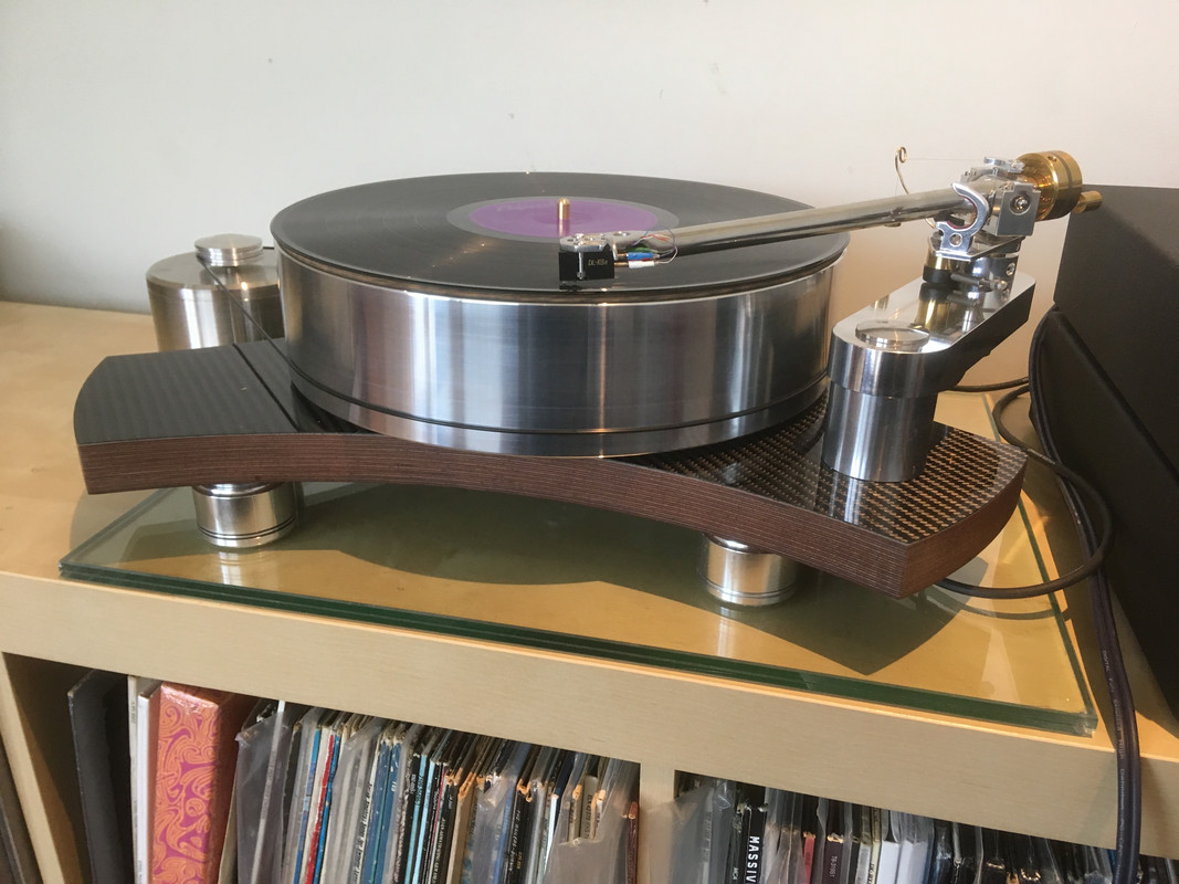
On the subject of Panzerholtz used for plinths here, finally , is my effort.
I will claim credit for the design but all the manufacturing was farmed out to much cleverer people than me. I need here to thank both Paul and Simon for their help and advice and also to Helen Bach ( who is not a Helen ) for his very very helpfully steering me towards simpler is better...the design started way over complicated and has been distilled down to ( I think ) simplicity itself.
A few details....
25mm thick B25 Panzerholz..which, I think is 40 ply. I tried to like the raw finish of the panzerholz but couldn't so the top surface is finished with a sheet of 0.6mm carbon fibre sheet. Next time I will just veneer it with something better looking.
Platter is one solid lump of aluminium 80mm thick and weighing 15 kilos.
The platter floats on two opposed 100mm wide ring magnets. One set into the plinth and the other set into the platter.
The 'bearing' is a vertical 12mm thick tungsten carbide shaft ground to a near mirror polish that goes into a very large oilite bushing set into the platter itself...very simple design.
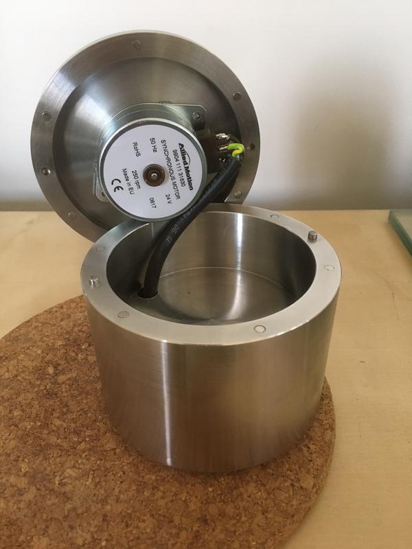
The motor is a 24v Rega motor that is capable of starting the platter off from a standing start with no manual assist.... but I tend to give it a nudge anyway. The motor pod is a hugely heavy lump of stainless steel... the motor is attached to the 'lid' of the pod and the lid is held in place buy a number of 3mm neodymium magnets. The pulley was machined to run either one or two belts. The motor is selectable for 33.3 or 45 at the push of a button.
The more I look at it the more I think that i will shorten the two non arm bearing wings of the plinth.At the moment they are all three the same length.
Not much else to say about it
Ah,yes.... at the moment it sits on maglev feet but I might change them at a future date.
I will claim credit for the design but all the manufacturing was farmed out to much cleverer people than me. I need here to thank both Paul and Simon for their help and advice and also to Helen Bach ( who is not a Helen ) for his very very helpfully steering me towards simpler is better...the design started way over complicated and has been distilled down to ( I think ) simplicity itself.
A few details....
25mm thick B25 Panzerholz..which, I think is 40 ply. I tried to like the raw finish of the panzerholz but couldn't so the top surface is finished with a sheet of 0.6mm carbon fibre sheet. Next time I will just veneer it with something better looking.
Platter is one solid lump of aluminium 80mm thick and weighing 15 kilos.
The platter floats on two opposed 100mm wide ring magnets. One set into the plinth and the other set into the platter.
The 'bearing' is a vertical 12mm thick tungsten carbide shaft ground to a near mirror polish that goes into a very large oilite bushing set into the platter itself...very simple design.
The motor is a 24v Rega motor that is capable of starting the platter off from a standing start with no manual assist.... but I tend to give it a nudge anyway. The motor pod is a hugely heavy lump of stainless steel... the motor is attached to the 'lid' of the pod and the lid is held in place buy a number of 3mm neodymium magnets. The pulley was machined to run either one or two belts. The motor is selectable for 33.3 or 45 at the push of a button.
The more I look at it the more I think that i will shorten the two non arm bearing wings of the plinth.At the moment they are all three the same length.
Not much else to say about it
Ah,yes.... at the moment it sits on maglev feet but I might change them at a future date.
Last edited:
Joe
pfm Member
Well done Joe. I'd love to see more build photos and drawings from bits you had made etc if you've got them. I'm especially interested in the build of the bearing and the math you had to do for the levitation.
Hi Stefan... thank you.
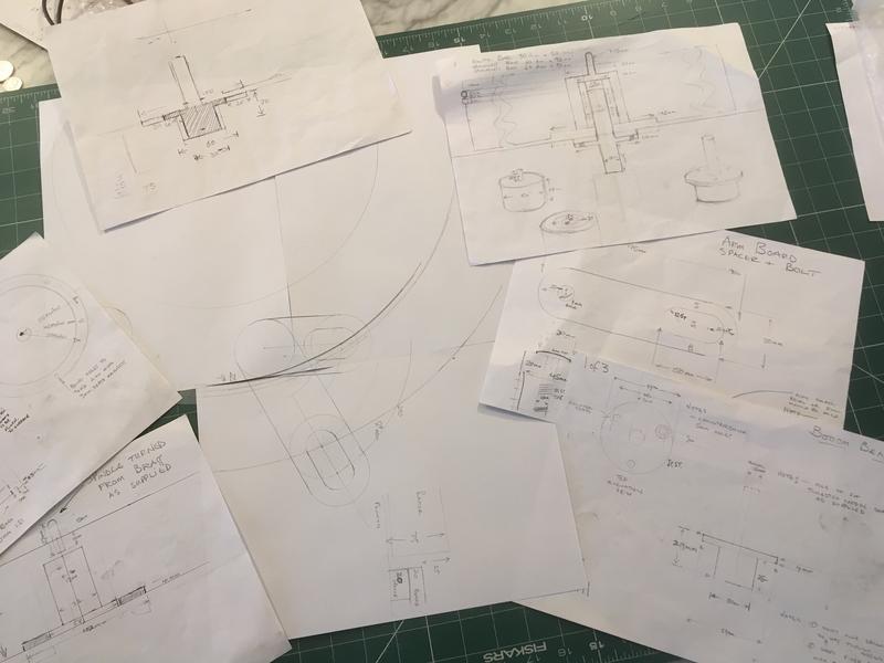
Drawings ! ! ? ..i am a back of a fag packet level bodger...I will include a photo of such drawings as there were.
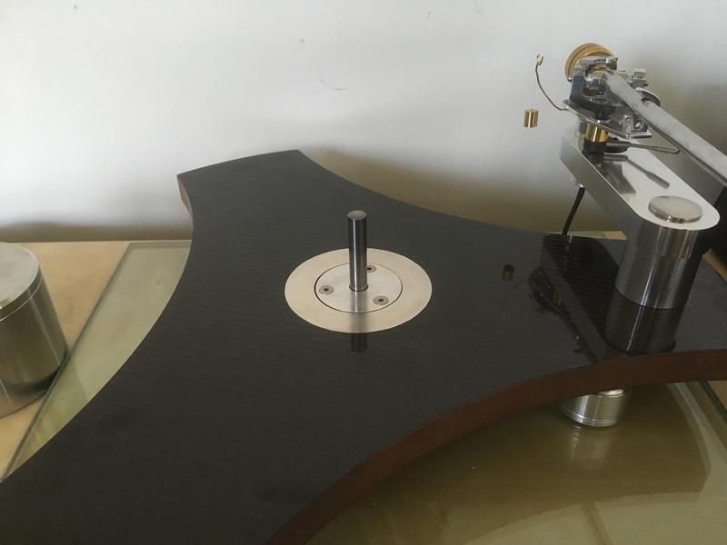
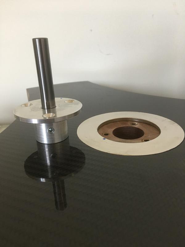
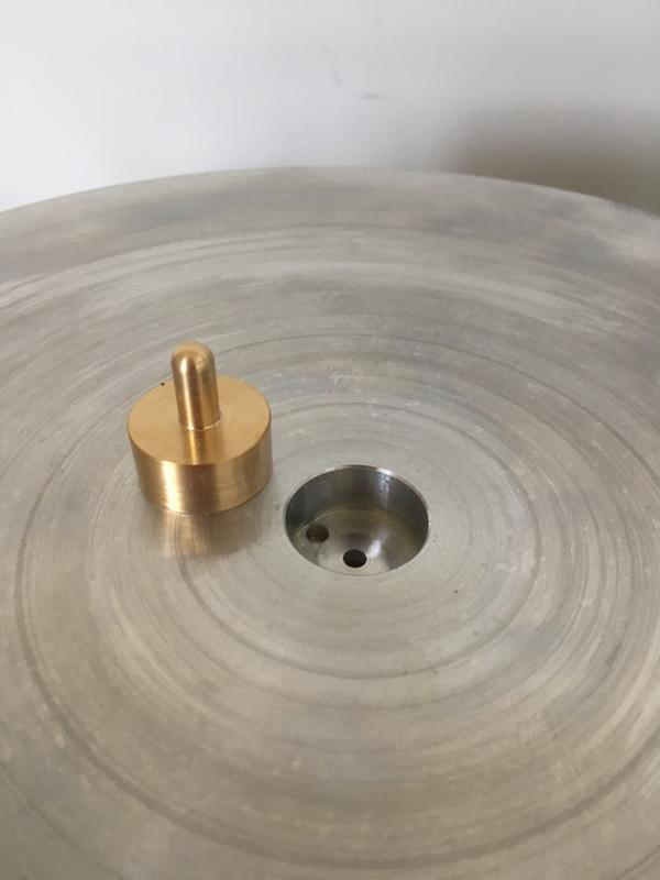
Here are some photos of the bearing spindle and housing and the magnet on the plinth and also the bottom of the platter showing the other magnet and the oilite bushing.
The underside of the platter... the magnets are 4mm thick and the plinth and the platter are machined so that the magnets are flush with each surface.

The Top of the platter... I designed the record spindle to be removable. A small hole was drilled through to the bushing both to allow air to escape when
lowering the platter onto the spindle and to allow periodic oiling of the bearing from the top. Not shown on the photos is a 12mm V seal that that fits over the bottom of the
bearing shaft to catch excess oil.
Whilst I am doing this I may as well show a picture of the motor housing... you can see how the 3mm magnets are fitted top and bottom and the pair of locating dowels.
The motor is literally stuck to the top of the housing with the sort of snot like glue strip that the bank use to stick your new credit card to the letter with.
Last edited:
Joe
pfm Member
I forgot... I can't take credit for the maths regarding the magnet. I searched the internet for quite a while before I came across this...
www.kjmagnetics.com/calculator.repel.asp?calcType=ring
it did the work for me.
Another useful webpage ... to calculate the pulley size....
https://www.blocklayer.com/pulley-belt.aspx
And another one to work out what weight your platter will be when machined
http://www.aalco.co.uk/online-tools/weight-calculator/
And...... magnets from here..
http://www.ebay.co.uk/itm/LARGE-Neodymium-Magnets-RING-CYLINDER-SUPER-MASSSSSIVE-NEODYM-Neodimio-Magnete/262787456693?ssPageName=STRK:MEBIDX:IT&var=561778005671&_trksid=p2060353.m1438.l2649
Last edited:
This site contains affiliate links for which pink fish media may be compensated.
Joe
pfm Member
So the bearing hasn't actually got an end as it were? It completely levitates and the contact is just the sides of the shaft and bearing housing?
Absolutely... that 15 kilo lump just floats beautifully 5mm above the plinth. It spins effortlessly. I think that there is a 10mm gap above the spindle in the bearing shaft but you can't compress the magnets that much when the platter is on so it never "bottoms out". You can see in the photo of the shaft and its housing the grub screw that allows for fine adjustment of the shaft height ( had to build such into the design as I was unsure as the the final height the shaft would need to be ) .
I chose a 12mm diameter shaft as a compromise between too thin to do a good enough job of 'gripping' that much weight and too thick ( say 20mm ) where the speed of rotation around 20mm would be too fast for the oil to do the best job of maintaining a constant film and not sheering.
The only friction in the bearing is the oil between the shaft and the bushing.
Helen Bach
if it ain't Baroque ...
Luverly job, Joe. I hope it sounds as good as it looks (or, I hope it doesn't 'sound' at all!)
May I use a pic as an exemplar of what can (should) be done, all credit given?
Just as a tiny comment, no criticism intended, I understand that the carbon fibre is an aesthetic consideration, but will not add to the goodness of the Panzerholz. The non-rectilinear design also reduces modal density.
One question, the magnetic bearing, is any part of the spindle magnetic? Could it have an effect on MC carts? I ask because I am looking at a design for a bearing which uses an oil-based ferrofluid and neo-magnet to keep some oil between the ball and thrust plate. However, the steel spindle becomes magnetic. I may try a non-steel ball, but just a thought!
Joe
pfm Member
Luverly job, Joe. I hope it sounds as good as it looks (or, I hope it doesn't 'sound' at all!)
May I use a pic as an exemplar of what can (should) be done, all credit given?
Just as a tiny comment, no criticism intended, I understand that the carbon fibre is an aesthetic consideration, but will not add to the goodness of the Panzerholz. The non-rectilinear design also reduces modal density.
One question, the magnetic bearing, is any part of the spindle magnetic? Could it have an effect on MC carts? I ask because I am looking at a design for a bearing which uses an oil-based ferrofluid and neo-magnet to keep some oil between the ball and thrust plate. However, the steel spindle becomes magnetic. I may try a non-steel ball, but just a thought!
Pictures... you can use any and all or if there is something specific you would like I can send you more.
I think that it doesn't 'sound' at all but then I don't subscribe to 'veils being lifted and inky blackness whatever... ' all I can say is that I have been playing records for 12 hours a day and really enjoying it.
I know that thing about the carbon fibre..I did take on board what you said when we conversed about materials choices ..like I say , I think that I will shorten two of the 'wings' and may take that opportunity to strip the carbon and just replace it with a wood veneer. ( or just build another plinth... now having the CAD cutting programme for it it will be a simple job.)
I did test the tungsten carbide rod/spindle and found it to be hardly magnetic at all. I was fairly anal about the materials choice such that the three machine screws that bolt the spindle housing down are titanium ( non magnetic ) and locate into brass threaded inserts ( non magnetic )... you get the picture?
I use MC cartridges and can detect no effect upon them at all... how much having 80mm of solid aluminium covering the magnets contributes to that I don't know nor have the necessary education to work it out... we need someone to chip in here and let us know.
hifinutt
hifinutt
just been reading a review of speakers made from this stuff , must look it out again , i have never heard of it before this . tankwood
https://www.kaiser-acoustics.com/en/speakers/chiara/chiara-review-hifiplus-2013-hr.pdf
https://www.kaiser-acoustics.com/en/speakers/chiara/chiara-review-hifiplus-2013-hr.pdf
sq225917
Bit of this, bit of that
There's no field to speak of at 80mm separation. I used to have my Rega P5 magleved with a 25mm acrylic platter and there was no increased antiskate or tracking weight effects close to the record end. Of course Joe's magnets area fair bit stronger than those I used to lift a 25mm plastic platter.
orangeart
KJF Audio Ltd.
Joe is the platter solid or have you hollowed it a little to try and keep the mass toward the edge to increase the moment of inertia?
I built a similar turntable years ago out of clear acrylic when such things were cool. The platter was about 50mm in the middle to support the bearing housing (from a project rmp9) then across most of the platter just about 15mm thick, at the edges about 25mm with 25mm brass rods tapped and bolted all the way round. I had another acrylic platter to that had holes around the edge filled with lead shot which was then encapsulated in clear resin. Both offered brilliant speed stability. Might make another deck at some point.
I built a similar turntable years ago out of clear acrylic when such things were cool. The platter was about 50mm in the middle to support the bearing housing (from a project rmp9) then across most of the platter just about 15mm thick, at the edges about 25mm with 25mm brass rods tapped and bolted all the way round. I had another acrylic platter to that had holes around the edge filled with lead shot which was then encapsulated in clear resin. Both offered brilliant speed stability. Might make another deck at some point.