
You are using an out of date browser. It may not display this or other websites correctly.
You should upgrade or use an alternative browser.
You should upgrade or use an alternative browser.
Thorens TD-124/II restoration / upgrade
- Thread starter Tony L
- Start date
-
- Tags
- idler drive sme 3009 td-124 thorens
Nagraboy
Ausculta fili
torstoi
pfm Member
Yep, the lower one in screw direction and the upper one in un-screw direction with light force till they virtually form a unit.
WD40 is not the best solution for severly stuck or rusted connections.
It does serve a variety of puposes 'so-so' but isn't especially good in any apart from water displacement perhaps.
Liqui Moly MOS2 is by far better to get severely rusted or stuck screws loose.
Should you not get the bolt out with a force sensible enough to not risk to break the bolt,
you can give a light , exactly vertical hit to the top of the bolt to crack up the tense joint in the base of the thread a bit..after that ideally apply Liqui Moly MOS2 and let it sink into the microscopic cracks over night.
Just gentle knocks is enough to vibrate the base lightly to let some solvent move in.
Ofc you need to place the deck on a cushion before you give the gentle hit to the bolt, so no surface gets damaged.
The second possiblity...especially if someone really glued the thing in with bomb-proof screw-lock,
is heat.
So the last means and the best working with superglue or screw-lock ultra would be a blowtorch.
Direct only at the end of the bolt, the heat will travel up to the problem area by itself, no need to point towards the deck in any way.
Good luck..
Tony L
Administrator
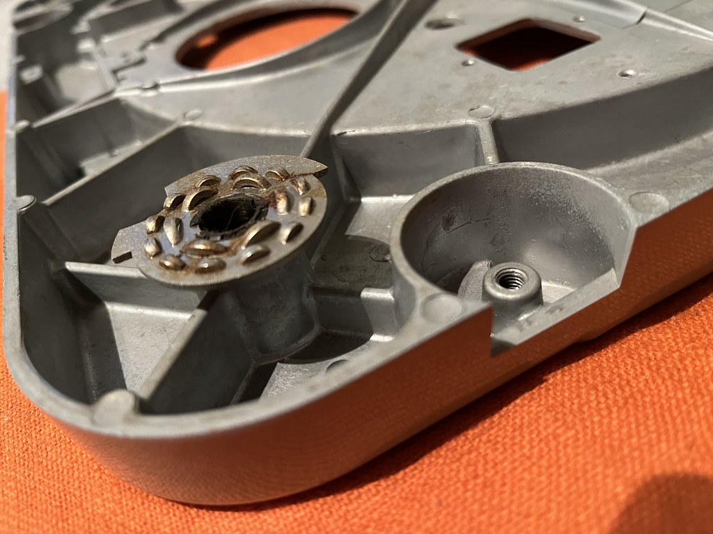
The steel rods will obviously be far stronger than the cast alloy chassis so if someone really has done something crazy with glue I’d be reluctant to risk cracking the threaded boss as if that breaks it is whole new chassis time really.
PS The thing that worries me here is they are apparently all stuck firm. That does not sound in any way normal to me. If anything it sounds deliberate.
PS The thing that worries me here is they are apparently all stuck firm. That does not sound in any way normal to me. If anything it sounds deliberate.
torstoi
pfm Member
Yes, I agree..the bolt isn't really big and my guess is someone used very firm screw-lock.
In which case I'd not try knocking, but solve the screw-lock by heat.
Possibly the best you see a mechanic with a blowtorch, as this would mean much less / no risk for your chassis if done right.
In which case I'd not try knocking, but solve the screw-lock by heat.
Possibly the best you see a mechanic with a blowtorch, as this would mean much less / no risk for your chassis if done right.
user510
pfm Member
'hope you don't mind my chiming in. Agree with Tony about the 50 hz pulley and a tight belt pulling the motor forward and putting those bracket shafts in contact with chassis material in the mounting holes. All isolation will be lost that way. I'd search for a looser fitting belt to alleviate that problem.See the wonky springs below. The shafts are a few mm to the right of where they should be.
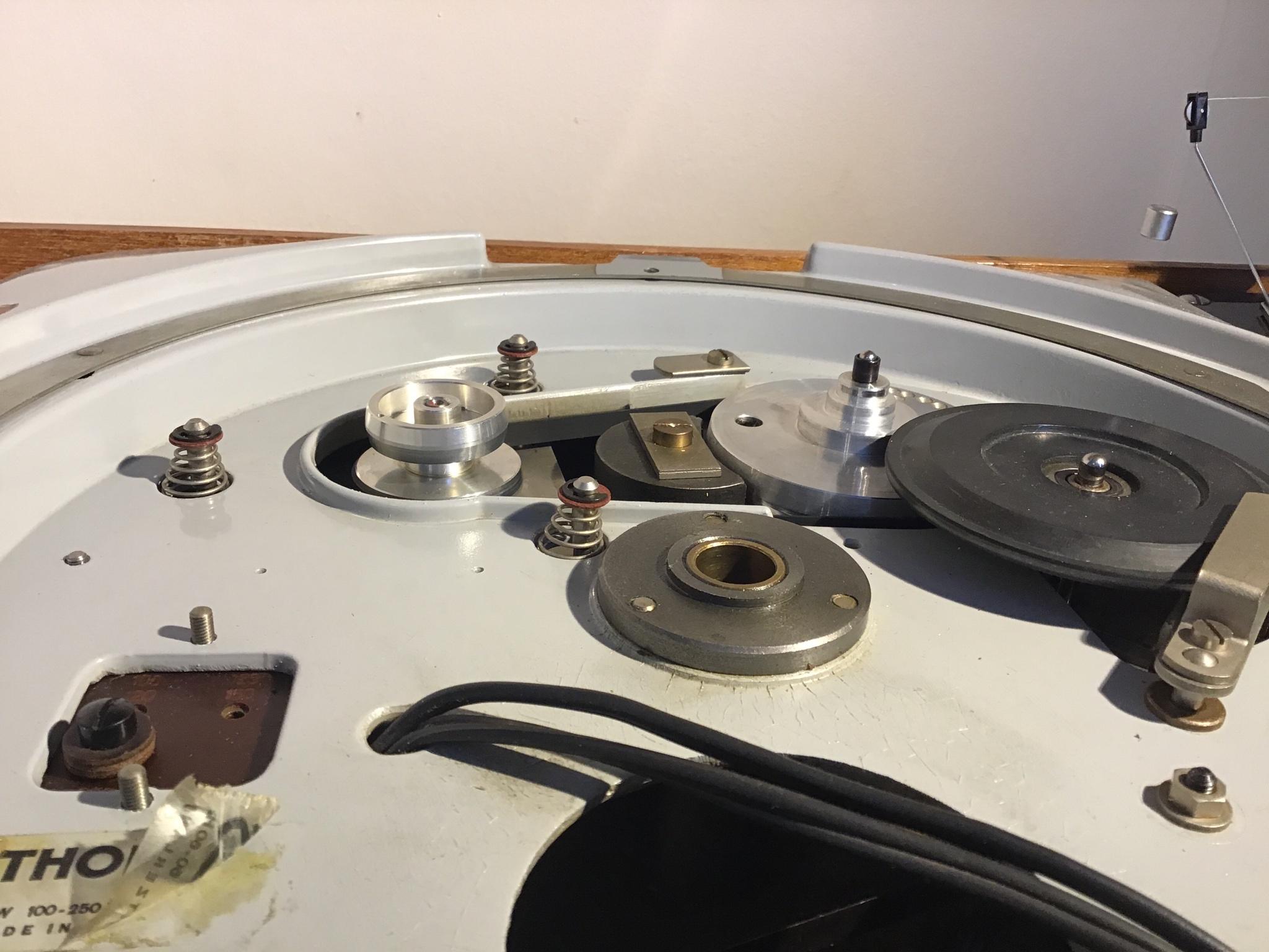
-Steve
Nagraboy
Ausculta fili
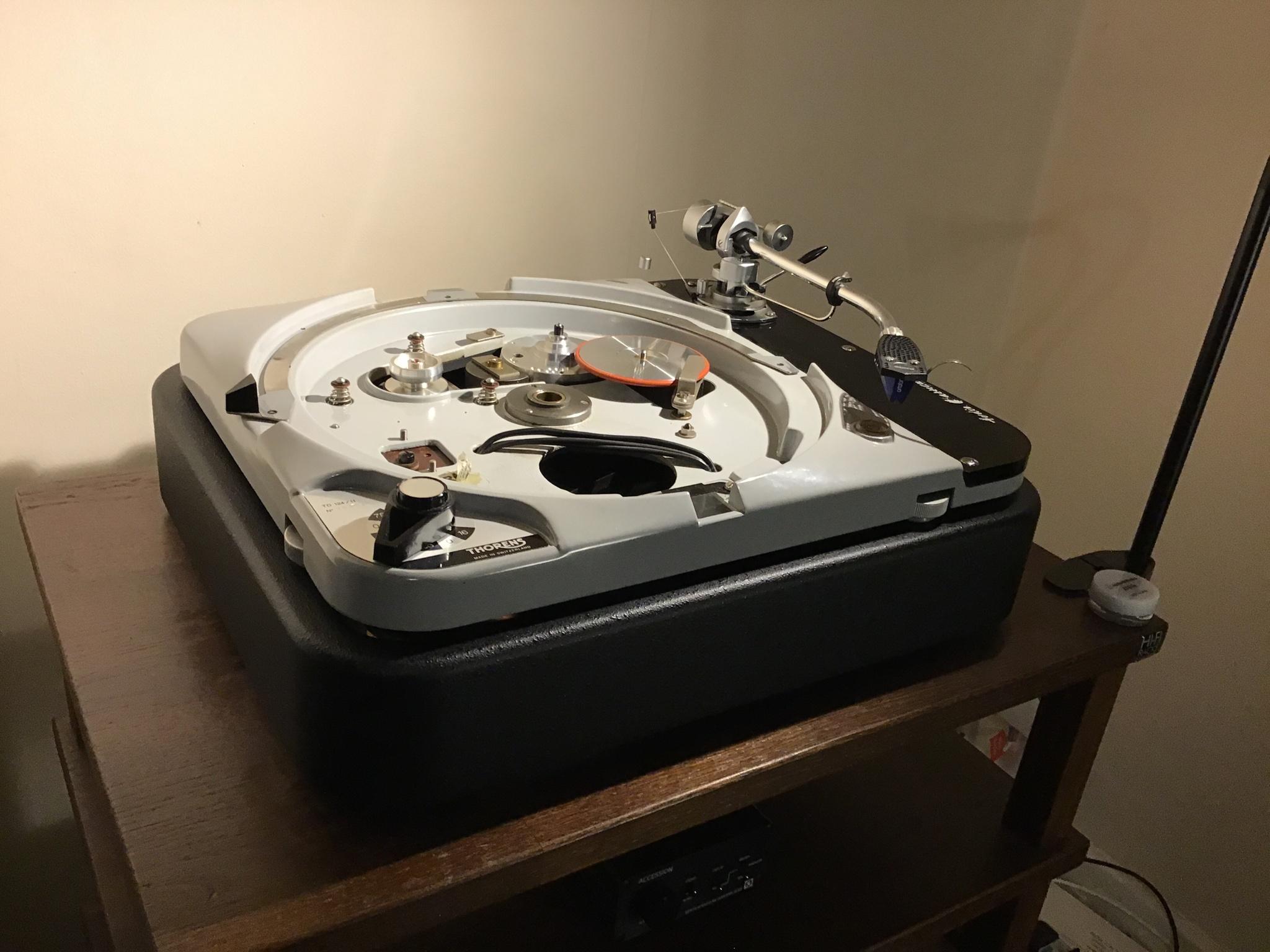
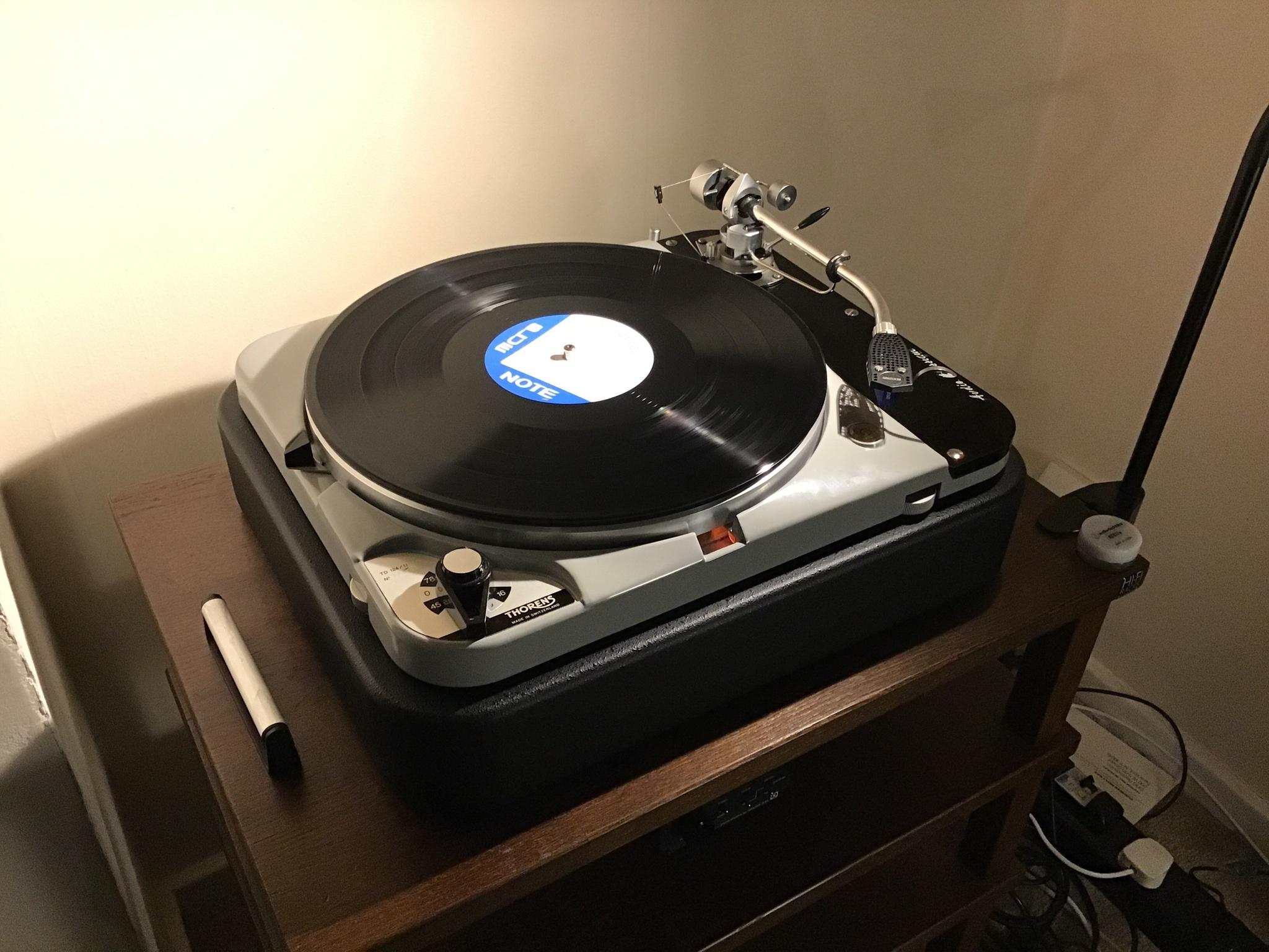
Right chaps. Turns out my local ScrewFix was open til 8pm tonight, so I went out and bought a set of spanners (hoping for the best) and a hacksaw (fearing the worst). Once at home with the spanners, and a pair of pliers I already had, I tried the 2 nuts method and without too much effort the bolt started to move! I’ve now removed all 4 tricky bolts and Tony’s suspicion was right - some idiot had glued them into the sockets. Fortunately with some careful control I removed all of them with no damage and the short length Swissonor bolts are now in place with the adjustment wheels intact. Next, lowering the deck into the new plinth:
Nagraboy
Ausculta fili
Just levelled the deck and about to play an LP (Freddie Hubbard, Blue Note) via the Graham Slee Accession’s variable output directly into a Quad 303 and Falcon LS3/5a.
With the new belt, springs - and maybe even the plinth - the noise has dropped by quite a large amount. There’s no ticking sound or low frequency drone anymore.
Wonder if the idler wheel and springs have helped with rumble?
First reaction is ‘Wow!’ The lower noise floor has made the music seem so much more dynamic and detailed. Seems more vivid and exciting than before, I’m happy with the result.
As for rumble, in between tracks I heard - not much to complain about. Was it the usual groove noise or the 124? Not sure, but I’m really happy with this turntable now. I just hope tomorrow when I fit the SME M2-9R and SPU #1S that things go more smoothly than today!
Thanks for all the help, it’s much appreciated")
With the new belt, springs - and maybe even the plinth - the noise has dropped by quite a large amount. There’s no ticking sound or low frequency drone anymore.
Wonder if the idler wheel and springs have helped with rumble?
First reaction is ‘Wow!’ The lower noise floor has made the music seem so much more dynamic and detailed. Seems more vivid and exciting than before, I’m happy with the result.
As for rumble, in between tracks I heard - not much to complain about. Was it the usual groove noise or the 124? Not sure, but I’m really happy with this turntable now. I just hope tomorrow when I fit the SME M2-9R and SPU #1S that things go more smoothly than today!
Thanks for all the help, it’s much appreciated
Nagraboy
Ausculta fili
It is always cumulative. Every little detail has an impact somewhere. Is it sounding good, i.e. that typical 124 ease, stability and solidity to things?
It is Tony, it sounds effortless and rock solid, with such rhythmic command - have to give some credit to the 3009 and 2M Blue where it’s due too. Can’t wait to put the new arm and cart on it tomorrow.
anubisgrau
pfm Member
how were kidney beans?
Nagraboy
Ausculta fili
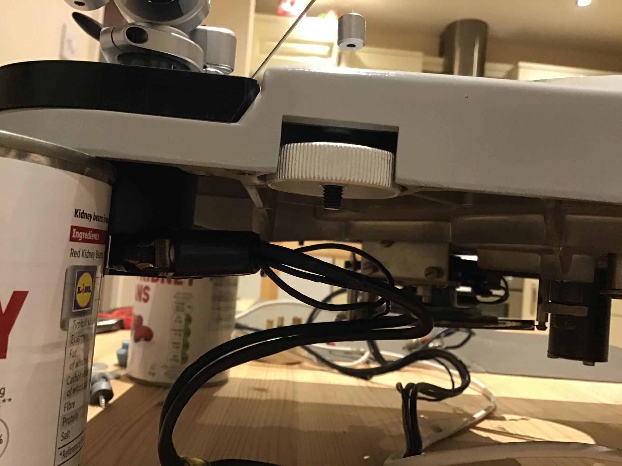
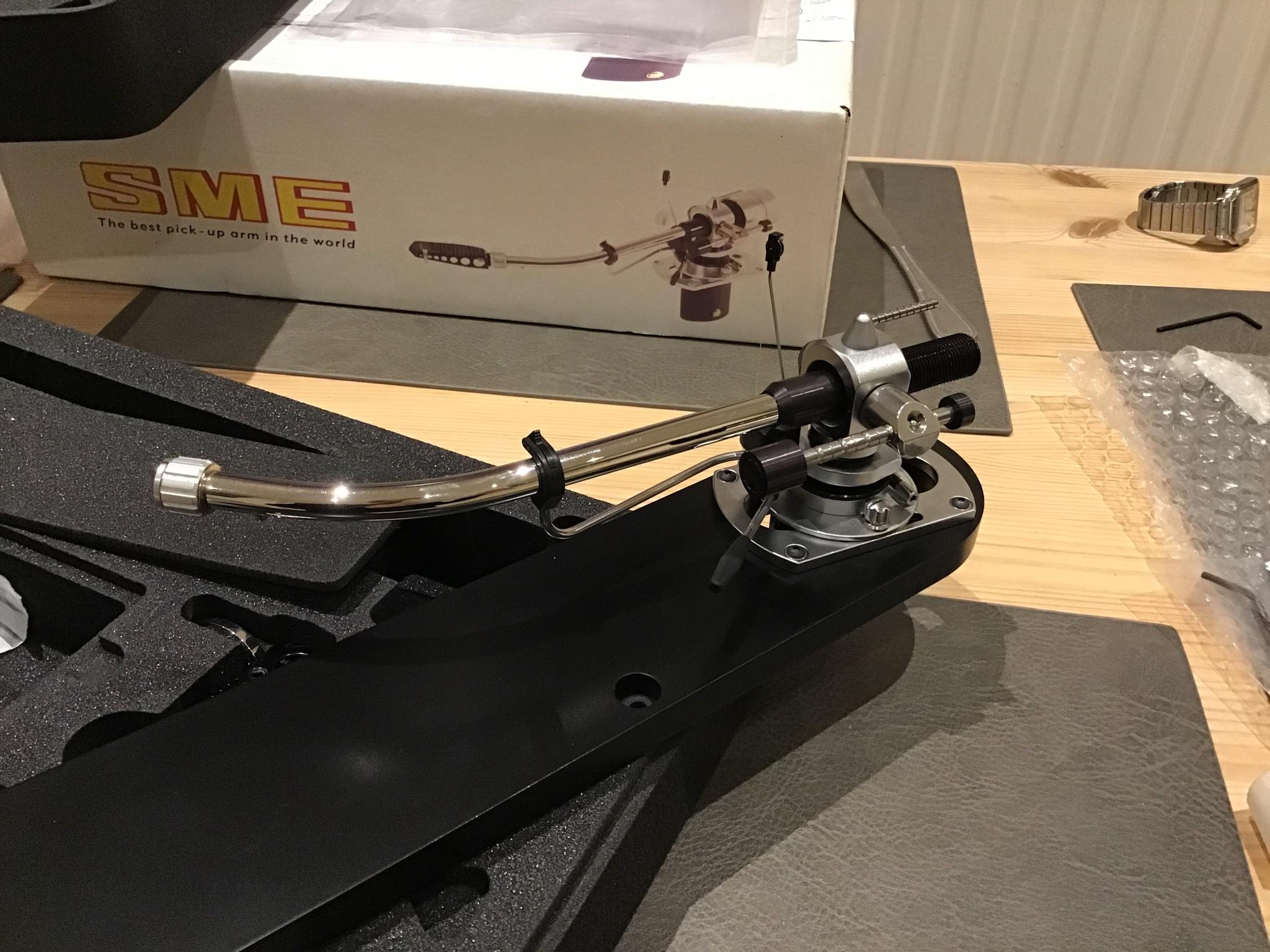
I’m setting up the SME M2-9R on the deck now. Does anyone know where the ground tag should go? The 3009 which I’d been using had it’s tag screwed to the TD 124 chassis grounding point, but the M2-9R manual shows the arm cable’s tag attached to the arm’s mounting cylinder thing near the arm’s phono output plugs.
I don’t have the original SME arm cable that would usually come with the arm, which has extra ground tags for the phono plugs at the SUT end. But I’ve got one with the usual single ground lead.
There might not be a definitive answer but is there a best practice/standard procedure way to do it? It’s got to be either tagged to the 124 chassis or the arm’s grounding tag.
Here’s the arm now attached to the Swissonor panzerholtz armboard:
torstoi
pfm Member
I would attach the arm cable's tag to the arm's mounting cylinder as SME wants to have it working.
And additionally I'd create a connection from the 124 chassis grounding point to said mounting cylinder
where it connects at the same point as the arm cable's tag. (as the TD124 'wants' it)
This way to my understanding there's less chance of any different potentials building up & creating hum problems.
Tony L
Administrator
The 3009 which I’d been using had it’s tag screwed to the TD 124 chassis grounding point, but the M2-9R manual shows the arm cable’s tag attached to the arm’s mounting cylinder thing near the arm’s phono output plugs.
Take it to the SME’s screening can as the SME manual states.
PS Further to the above post I’d not common the 124 and SME grounds. Leave them separate. The feature existed back when the 124 was supplied with the original issue and now illegal two-core mains lead. Assuming the turntable chassis is correctly grounded via a three core mains cable there is an advantage in keeping them separate (no chance of an earth loop etc). The only time I’d reconsider this is if for some reason the pre/phono stage does not have a mains earth, e.g. battery or wall-wart phono stage, passive pre etc.
Nagraboy
Ausculta fili
Ok I’ll move it to the screening can. That’s a shame because it was rather tricky getting under there and removing one cable and attaching another ground cable.
I might have a spare ground lead laying around to add the extra chassis to screening can connection. Should I leave that one for today or do you think it is essential?
I might have a spare ground lead laying around to add the extra chassis to screening can connection. Should I leave that one for today or do you think it is essential?
Nagraboy
Ausculta fili
Take it to the SME’s screening can as the SME manual states.
PS Further to the above post I’d not common the 124 and SME grounds. Leave them separate. The feature existed back when the 124 was supplied with the original issue and now illegal two-core mains lead. Assuming the turntable chassis is correctly grounded via a three core mains cable there is an advantage in keeping them separate (no chance of an earth loop etc). The only time I’d reconsider this is if for some reason the pre/phono stage does not have a mains earth, e.g. battery or wall-wart phono stage, passive pre etc.
Ah just read your update Tony. That makes sense! The mains cable was replaced at last service so is a correct three pin affair. It’s funny though, as that service guy was the one who attached the ground cable to the chassis ground and the arm didn’t have a grounding cable at all.
*** Just opened up the 124 mains plug and there is no earth wire in there at all. I guess he didn’t sort it then! So I guess I’ll still need the chassis ground lead then?
Tony L
Administrator
I’d leave them separate assuming you have a good preamp earth and the chassis is grounded. It also makes life easier as you can so easily remove the whole arm/armboard assembly from above! Just three screws and its off!
PS Pay attention to the tension of the three armboard screws too, they just want to be nudged-up until they stop IMO, definitely not ‘tight’. Definitely one to set by ear.
PS Pay attention to the tension of the three armboard screws too, they just want to be nudged-up until they stop IMO, definitely not ‘tight’. Definitely one to set by ear.