
You are using an out of date browser. It may not display this or other websites correctly.
You should upgrade or use an alternative browser.
You should upgrade or use an alternative browser.
QUDOS - the brilliant new amplifier boards from Avondale
- Thread starter misterc6
- Start date
Chops54
pfm Member
Heres my solution to fitting the BD237 to the NCC200. It goes in the same place as it does in the Qudos. As you can see I drilled three holes just in front of the heatsink. That's it!
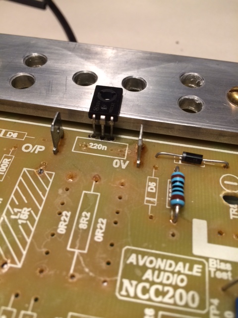

You might just have to sneak that 220nf cap forward a touch but there's plenty of room for it. Flying leads will go under the board.
You might just have to sneak that 220nf cap forward a touch but there's plenty of room for it. Flying leads will go under the board.
Luca
pfm Member
Heres my solution to fitting the BD237 to the NCC200. It goes in the same place as it does in the Qudos. As you can see I drilled three holes just in front of the heatsink. That's it!
You might just have to sneak that 220nf cap forward a touch but there's plenty of room for it. Flying leads will go under the board.
My aim is to put a regulating circuit for the front end under the board. So the 40 x 40 profile gives me a little more room. However, I like your solution. What kind of drill bit do you have used?
Last edited:
Here's the solution that I settled on for TR5
https://flic.kr/p/2jgoDCu
I was thinking about converting these version 1.4 boards to Qudos a while back, along the lines that Chops54 is describing
This gives me the confidence that it can be done, thanks Chops54
Remember that TR5 will need to be electrically isolated from the heat sink so check the mounting pad for continuity with a meter as there are different types
Luca
pfm Member
Here's the solution that I settled on for TR5
https://flic.kr/p/2jgoDCu
I was thinking about converting these version 1.4 boards to Qudos a while back, along the lines that Chops54 is describing
This gives me the confidence that it can be done, thanks Chops54
Remember that TR5 will need to be electrically isolated from the heat sink so check the mounting pad for continuity with a meter as there are different types
Hi Mark, nice and easy solution.
I see you have not still removed R4, R27, C9 and C10 from the converted Qudos board. Is it not worthwhile?
James Evans
Bedroom Bodger
For some reason my DVMs are refusing to measure anything when put in the +ve line and it looks like they are not passing the supply voltage through either. Odd. If measuring across the +ve emitter resistor I'm assuming around 26mV is what we're looking for?Your welcome James. Front end pulls roughly 12mA. Alan uses two DVMs when he sets his.
Luca, the picture that I have linked to is a v1.4 Board that has been changed to v1.5 with the exception of a 330pf and a 3k that need changing to 220pf (C14) and 2k7 (R12). (R2) 22k has been changed to 1k, (R23) 2k2 changed to 1k2 and the bias current wound up to 130maHi Mark, nice and easy solution.
I see you have not still removed R4, R27, C9 and C10 from the converted Qudos board. Is it not worthwhile?
Luca
pfm Member
Luca, the picture that I have linked to is a v1.4 Board that has been changed to v1.5 with the exception of a 330pf and a 3k that need changing to 220pf (C14) and 2k7 (R12). (R2) 22k has been changed to 1k, (R23) 2k2 changed to 1k2 and the bias current wound up to 130ma
Hi Mark, I was referring to your post #915. Don't you try that mod?
I was also advised that R4, R27, C9 & C10 could be removed on the Qudos boards, doing so adds a further degree of refinement. It’s also worth pointing out that all of these mods are applicable to the HackerNap. There was a little discussion on here about the paralleling of output transistors
In the images of recent production Avondale NCC 220 modules there is nothing on R4, R27, C9 and C10. I'm interested to know if somebody has tried this modification and if it is worthwhile.
It was also suggested to me that R4, R27,C9 & C10 could be safely removed on Qudos boards but have seen that they are back in on the latest production run as seen on the Facebook page. However I’m not sure what would be the effect on NCC200 boards and without having the necessary measuring equipment to check the stability I would not make that change. I’m sure that there are others on the forum that would have more of an idea.
With regard to setting the bias on a Voyager I used two meters and added the readings together to get the 36mA that was recommended
With regard to setting the bias on a Voyager I used two meters and added the readings together to get the 36mA that was recommended
Luca
pfm Member
It was also suggested to me that R4, R27,C9 & C10 could be safely removed on Qudos boards but have seen that they are back in on the latest production run as seen on the Facebook page. However I’m not sure what would be the effect on NCC200 boards and without having the necessary measuring equipment to check the stability I would not make that change. I’m sure that there are others on the forum that would have more of an idea.
With regard to setting the bias on a Voyager I used two meters and added the readings together to get the 36mA that was recommended
Yes, it is better don't risk without to check the stability by the necessary equipment. I hope to get an answer from who has the proper instruments.
https://flic.kr/p/2jgspiR
Here's a link to the Qudos board prior to snipping R4 & R27 at one end, allowing them to be easily be soldered back if i did not like the result.
They are still out of the circuit and have been for a good number of weeks
Here's a link to the Qudos board prior to snipping R4 & R27 at one end, allowing them to be easily be soldered back if i did not like the result.
They are still out of the circuit and have been for a good number of weeks
Chops54
pfm Member
Those three components either side form some sort of filter. The two resistors and two caps are there on my NCC300 circuit diagram but Les crossed them out and told me they weren't required. However the NCC300 circuit is very different to the Qudos circuit. I know just the person to ask ")
Yes, supplied as bare boards. But not recentlyCan I ask if you bought those direct from Avondale?
337alant
Negatively Biased
JamesFor some reason my DVMs are refusing to measure anything when put in the +ve line and it looks like they are not passing the supply voltage through either. Odd. If measuring across the +ve emitter resistor I'm assuming around 26mV is what we're looking for?
Sounds like the DVM internal fuse has blown for your DC Milli Amps range ?
Alan
James Evans
Bedroom Bodger
Thanks Alan, yes, I was thinking the same. I'll have to check that. The boards have been built and used for some time now, just putting in a new case, so just double checking everything. Using the emitter resistor method I'm showing about 122mA on each channel.James
Sounds like the DVM internal fuse has blown for your DC Milli Amps range ?
Alan
DC offset was always and is a bit high at 73 and 61, although not the end of the world. Out of interest, what % difference in TR1/2 are folks using?