advertisement


AD815 preamp build thread

Hi Carl,

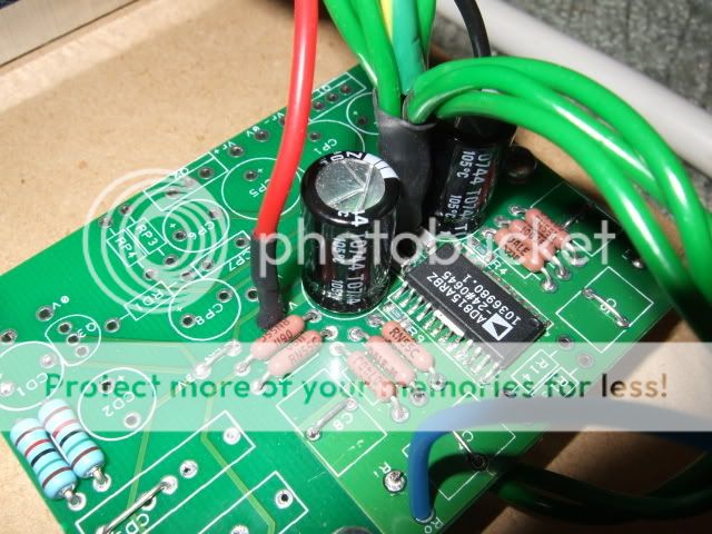
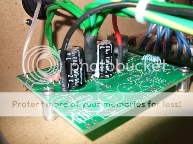
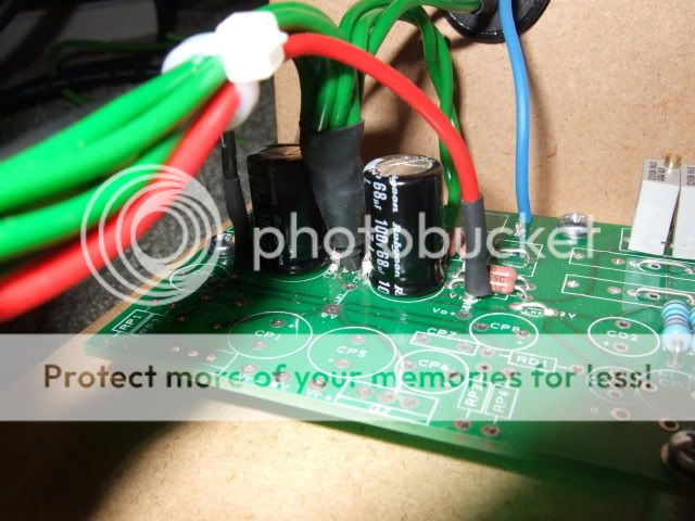
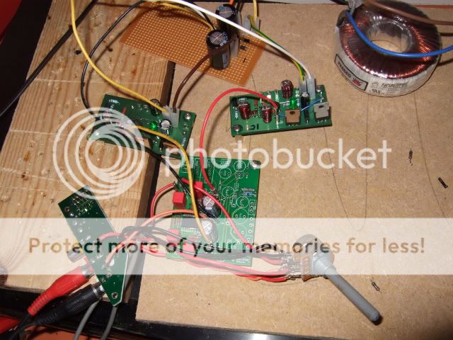
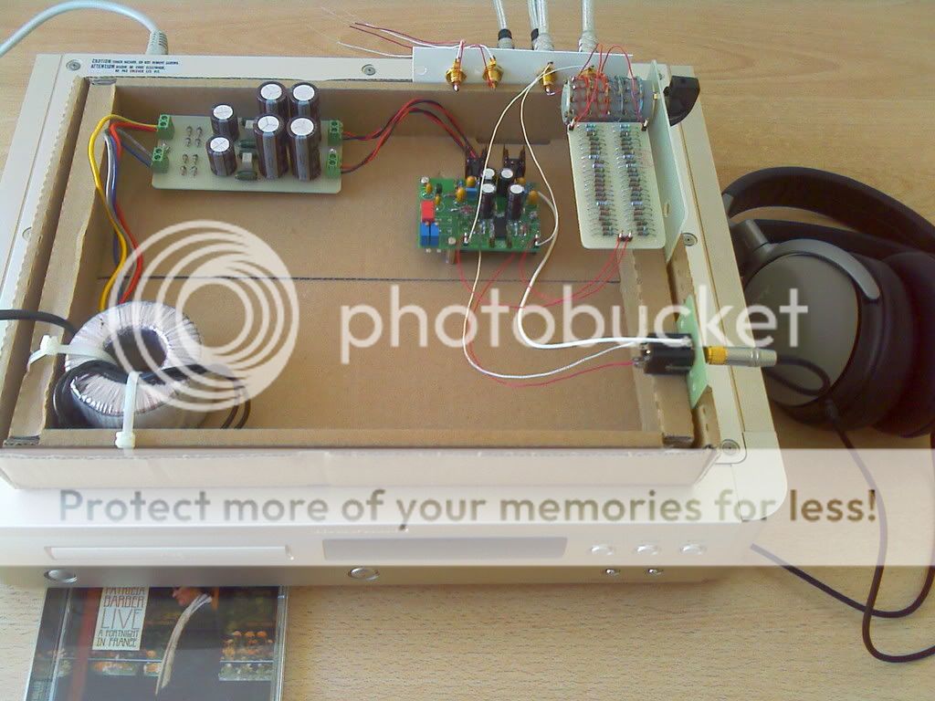
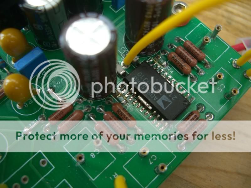
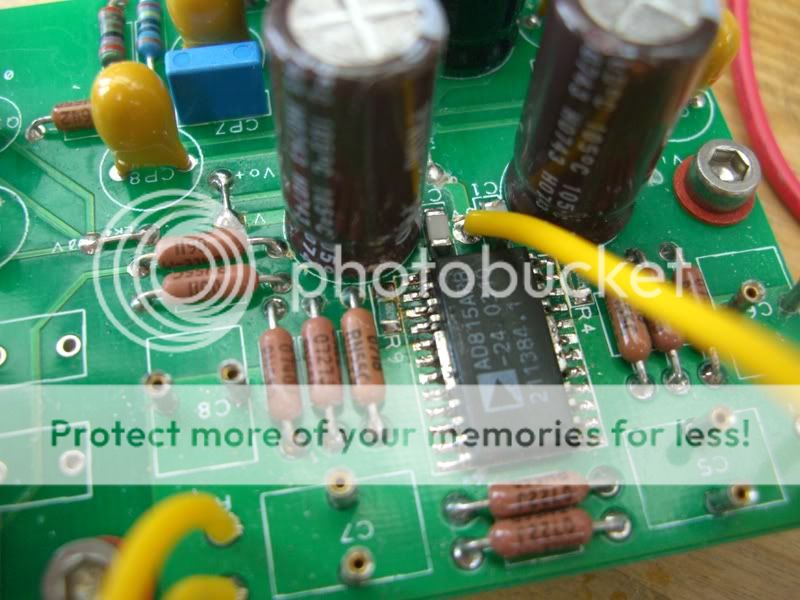
Thanks for the pointer. I had a check and I don't see any bridges. Here are some pics - hopefully you chaps might be abe to spot something I didn't. :D

Cheers

Jon

CIMG0016.jpg


CIMG0017.jpg


CIMG0020.jpg


Hi Jon,

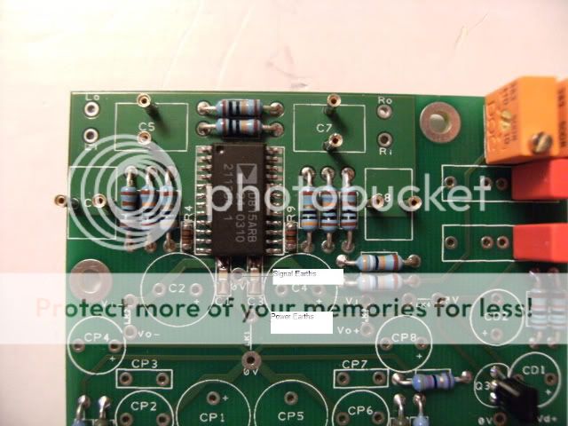
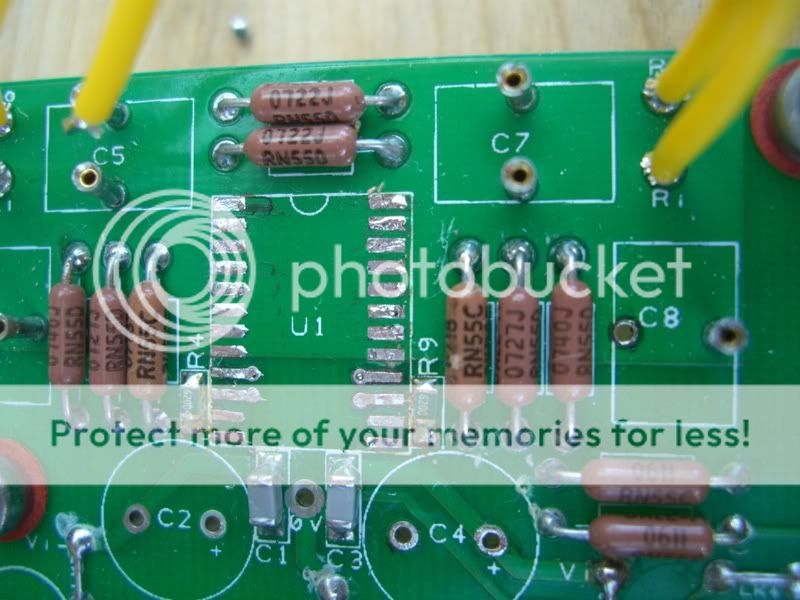
Have you checked that the lower pad of the SMD resistor R9 isn't bridged to pin 13? That would cause the effect you're experiencing. Same for a bridge between pins 13 and 14.

Other than that, it may be that you have a duff opamp :(

Good luck with it, and post some pictures when you can.

Cheers,
Carl
 
Here's some close-ups of the AD815 board. All of the 0V points in the preamp are starred at the 0V star on the PCB. The 0V input from the raw supply, both 0V connections from each of the superregs, the left/right 0Vs from the attenuator, all of them are bundled tightly and soldered together:

DSCF2536.jpg


They're attached to the PCB by way of a single leg from a 1W resistor; I chopped off the resistor's leg, then inserted it into the middle of the bundle of 0V wires. It's wrapped up nicely in heatshrink, then soldered directly to the PCB:

DSCF2535.jpg


The power cables are soldered to pins that go through the PCB, and the signal wires are soldered directly to the PCB. You can't see the signal input wires because they run underneath the PCB and are soldered on the top side of the board:

DSCF2539.jpg


One thing the observant may have already noticed is that this PCB has been modified:

DSCF2537.jpg


When I was originally putting it together as a kit 4, I wanted to increase the effectiveness of the RC filter in the DC nulling circuitry. To this end I fitted 10uF MKS2-XL caps, but they didn't fit in the standard holes. Instead, they were put into the holes closest to you in the above picture, the wire links makes sure they're connected to the circuit andm very importantly, the tracks underneath that link the two holes were cut. These mods give me enough room to fit the larger caps, but it turns out they won't be used.
 
Thanks, Carl. How may wire links do you have in total, I counted six is that the lot?

Regards,

Mus
 
There are 7 links on that board, but only 4 of them are actually being used: the wire links in place of the coupling caps. The others are the 2 I mentioned earlier, plus a link from the DC null 0V star to the main 0V star. It's not needed and does absolutely nothing, I just left it in circuit because it's neater that way.
 
From what I learnt about the importance of power and signal earths when I put a pair of 323 cards in a box; wouldn't it be better to star earth the power earths in one hole and the signal earths at the other.

DSCF0442-edited.jpg
 
I had considered that option, but I went with the datasheet implementation:

star-earth.png


The above image is copied straight from the datasheet and shows all the signal + power earths connected together in a star, so that's what I tried to implement.

Cheers,
Carl
 
Hi,

Here's a quick update: I decided to remove the AD815 to see if there was a bridge underneath the IC. There wasn't. OK, now I'm getting puzzled! ;) Even using an eyeglass, I cannot see any bridges - the pads are clean. And yet, Pin 16 is still connected to Pins 1-8 and 17-24. I think I have either overlooked something, or perhaps there is an internal connection being made. :confused: Dunno - I'm running out of ideas, though the process has been a good learning experience. :cool:

I'll post a pic tomorrow when the light is better......

Any further suggestions, please?

Cheers

Jon
 
Hi Jon,

I got out my spare AD815 and did some tests with my meter's continuity check across the following pins. The + probe was always on the pin in the left column, the - probe on the second column:

Pin 13 / [5-8]: Short
Pin 13 / 16: Momentary connection, then no continuity (right signal side of the amp)
Pin 13 / 14: No connection
Pin 13 / 15: No connection
Pin 13 / 9: Momentary connection, then no continuity (left signal side of the amp)

Pin 13/16 and 13/9 should measure identically. Do they? If they're different then your opamp is definitely knackered.

If you need me to measure anything else, just let me know.
Cheers,
Carl
 
Hi Carl,

Thanks for running those checks. I'll try them on my opamp later on, but I'd be interested to know if on a bare board whether Pin 16 is connected to Pins 1-8 and 17-24?

Cheers

Jon
 
There should be no connection on a bare board.

One thing springs to mind... the DC nulling circuit could, in theory, if improperly connected, put too much DC across the signal path. Can you take a picture of the entire board, top and bottom please? We'll see if we can debug it that way.

Cheers,
Carl
 
Hang on, are you saying the pins are bridged on opamp or on the board? I'm not clear any more!
 
Hi Carl,

It's a bridge on the board. I've been having a further diagnose and have isolated the problem. I was going to measure the AD815, but it's not necessary now - I also had to cut the legs to desolder it, rather than lift the tracks. I really ought to get some wider tips for my smd tweezers! ;) First I cut the track on the underside leading from the input DC blocker to the Pin 16. As I progressed, it became clear that the problem was "upstream".

Cut tracks here:

CIMG0023.jpg


It seems that the through hole plating on C8 (downstream leg) is making contact with the plane that Pins 1-8 and 17-24 sit on (heat sink).

Pic here:

CIMG0021.jpg


So, my solution will be to drill the hole out and sleeve it with some teflon. A drop of solder on the cut tracks and I'm home and dry! :cool:

Thanks for your suggestions. I've learned a load about diagnosing problems this time, so a worthwhile exercise IMHO! :D

Anyone know a reasonable source for AD815s, please?

Cheers

Jon
 
Of course it's fair to comment! You're comparing a non-optimal AD815 to a non-optimal Starfish, so that's fair game I reckon ;)

Ok. I will give the AD815 a few more days to run-in and will report back.

Didn't you have an AD815 and Starfish at the same time? What did you think of them?
 
Another work in progress... Head amp.
Having no camera on hand, I did the pic with my phone, sorry for the bad quality. I ensure you that it's not to hide my soldering job.

IMAGE_047.jpg


The board is feeded by a CRC psu and the original regulators. It is fully dc coupled, has the dc nulling circuit activated and makes my SONY MDR CD3000 singing marvelously well.
I'm using a 24 step shunt attenuator of my own at the input. The constant shunt resistors are inserted at the C7/C8 location with some re-routing and of low value(274R) to keep the noise level as low as possible. My cans are low z (32R) so I reduced the output resistors R3/R8 to 10R. Another change was to tweak the dc nulling components, RD4 to RD7. With low input resistance like my attenuator or the Joshua tree att. of Pears Audio(750R), the original components are inefficient to null output DC.
The one that Carl and some others are using has an high enough output resistor of 9K and will allow an easy setting. On my own board, with DC nulling deactivated, offset is 50mV. With RD4/5=5K and RD6/7=100K, I can now null dc even with inputs shorted and without added noise.
The bad thing is that it takes a long time to settle after power on. But once fixed, whatever the attenuation, it stays nicely between +/-2mV.

Nevertheless, I will add a dc servo and a delayed relay.

A second board is waiting but not mounted yet. It will be a preamp preceded by an input buffer (LME49860) and a Pears Audio attenuator. This one has no IR remote control. Actually I build a pic card and write the code for that purpose, but I'm not programmer by trade and it becomes somewhat messy...

I like what's actually coming out of my cans. Clean, detailed, strong bass. When I listen to headphones, it's for hearing things I'm not able to hear with my loudspeakers, discovering the ultimate richness of a recording. The purpose is reached with your boards, Carl. I just have to find a more decent case...


Happy listening to all of you,
Francis
 
Very nice, Francis! Thanks for posting :) I like the idea of reducing the resistors in the DC nulling circuit, perhaps others on the forum might have luck with similar mods. Your home-made attenuator looks good, too. Where did you get the stepping attenuator?
 
Hi Carl,

The switch comes from an old telecom system. For a diyer, it's good to have some opportunities at work.
I just tested the amp at power on/off. Previous amps I built, didn't perform well in this regard. With my HD580 (300R), there's nothing I can hear. The Sony cans are somewhat more sensitive and there's a tiny crackling noise some few seconds after power off. So nothing to worry about and this amp will stay as is, it's close to perfect.

Francis
 
My AD815 is up and running. I'm using the inbuilt regulator, fed from a +-27v power supply we built this weekend - just a transformer, rectifier and smoothing capacitors. I haven't implemented the DC nulling circuit at all yet. The only change to the power supply was to reduce voltage down to 15v.

I left it running yesterday and last night to run in a bit, and had my first serious listen this am. There is loads of detail, dynamism and transparency, but what I'm not hearing yet is the toe-tapping sense of rhythm that my 72/250 has, even though this has a much muddier sound.

I've now done a direct A/B between the 72/250 and 815/250. At the moment, the 72 is still better than the 815 - slightly less detail but overall more convincing musically. Wondering if the 815 needs even longer to run in - though can't remember any comments on long run ins.


Thanks again for a well put together kit - worked first time!
 
I tried the AD815 Preamp and made several revisions to the board.

While I usually find preamps benefits from a buffer before the volume potentiometer (Like NAIM does in all the NAC's)-
This isolates the output stage of the source from the potentiometer and make easier for it to drive the preamp. (Preamp with a buffer before the potentiometer tend to have a more dynamic sound character).

I have tested some capacitors for the decoupling and value for output resistor- In my circuit the AD815 stayed stable without oscillations in the range of 22R to 68R- I suggest keeping the 34R as a default and if you see the AD815 get into oscillations (use a scope or see if it's getting hot to touche)- increase the output resistor.
Better sound and more dynamic and vivid will be in the lower range (down to say 20 ohm- use this if you have a short and low capacitance interconnect connected at the output.

I've added a simple RC input filter in order to avoid RF get into the AD815 (1k and 1nf polystyrene in the input as you can see in the pictures in the bottom of the PCB).
(The stepped attenuator used in the NAC72 before).

I found Os-con or Rubycon zl/za a little bit better then the nichicon. if you want to be in the safe way- you can add some 0.3R resistor to avoid any resonance with the ceramic NPO capacitor connected in parallel.

Of course if you want to use the buffered AD815 you should have two boards (with the benefit of dual mono use of each AD815).

I find the Buffered AD815 sound very good- Clear and crisp.

Many Thanks Carl for bringing that Nice AD815 PCB to life! :)

Enjoy!

Avi

P5150995_s.jpg

P5150989.jpg

P5150993.jpg

P9200246_s-1.jpg


advertisement


Back
Top