Ok, the last thread got enormous and was concentrating around the design and buying of bits. Let's have a thread just for building, asking questions, fixing bugs, tweaking, etc etc etc.
First up, I've copied this from the other thread:
IMPORTANT INFORMATION
SMD components are hard to recognise, so I colour-coded them. Here's a Kit 1:
The 620R SMD resistors are coloured pink.
The 330R SMD resistors are coloured greenish-yellow.
The 0.1uF SMD capacitors are in the clear plastic, and they're not coloured at all.
The kit 2 is similar, but it contains an extra 4 caps an extra 2 resistors.
The kit 3 looks like this:

The 0.1uF film bypass caps for the PSU are blue. You'll need a multimeter to measure the resistors I'm afraid.
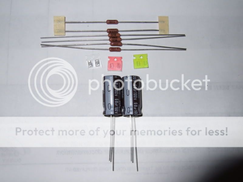
The kit 4:

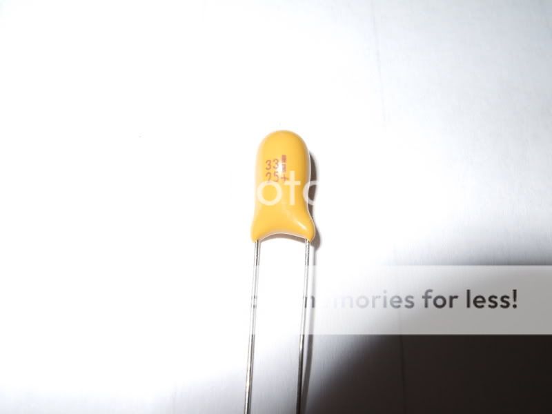
The small tantalum beads can be identified as follows. 33uF/25V:
The 10uF:
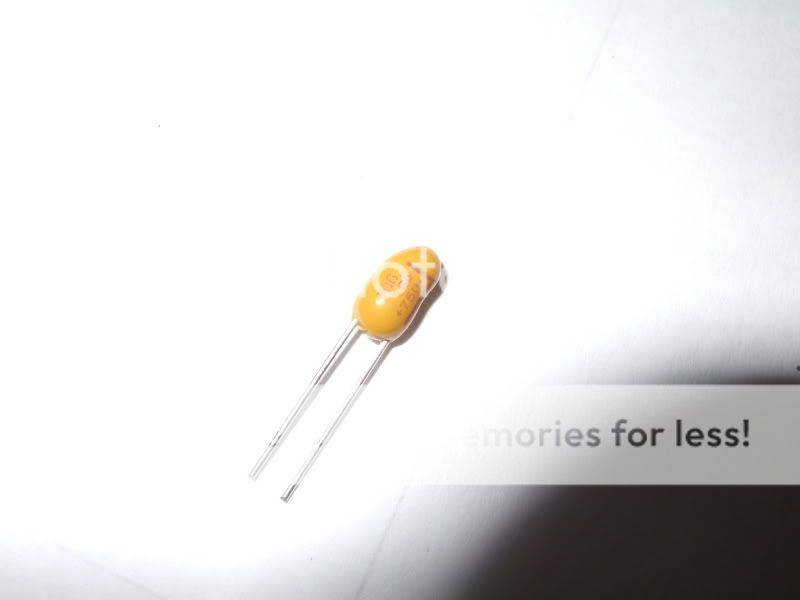
The 0.22uF:
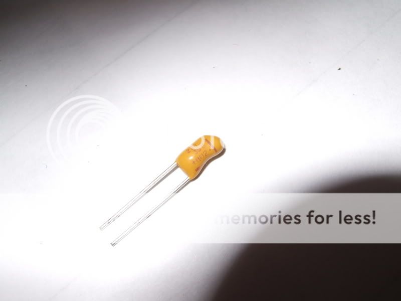
The positive (+) legs are marked with a + symbol.
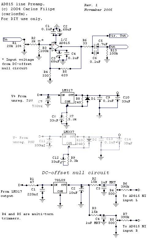
This is the schematic (the PCB doesn't have the protection diodes in the PSU circuit, they're not needed @ < 25V):
Cheers,
Carl
First up, I've copied this from the other thread:
IMPORTANT INFORMATION
SMD components are hard to recognise, so I colour-coded them. Here's a Kit 1:
The 620R SMD resistors are coloured pink.
The 330R SMD resistors are coloured greenish-yellow.
The 0.1uF SMD capacitors are in the clear plastic, and they're not coloured at all.
The kit 2 is similar, but it contains an extra 4 caps an extra 2 resistors.
The kit 3 looks like this:
The 0.1uF film bypass caps for the PSU are blue. You'll need a multimeter to measure the resistors I'm afraid.
The kit 4:
The small tantalum beads can be identified as follows. 33uF/25V:
The 10uF:
The 0.22uF:
The positive (+) legs are marked with a + symbol.
This is the schematic (the PCB doesn't have the protection diodes in the PSU circuit, they're not needed @ < 25V):
Cheers,
Carl