
You are using an out of date browser. It may not display this or other websites correctly.
You should upgrade or use an alternative browser.
You should upgrade or use an alternative browser.
AD815 preamp build thread
- Thread starter hacker
- Start date
I have amplification! 
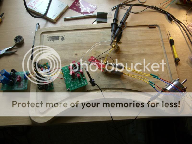
Built today with just the op amp section on the board. 10uF film caps and parallelled 1R2 in place of the links. Lash-up power supply using 317/337 based Jaycar board set to +-12V, then run through pos/neg JLH ripple eaters. Seem to have a little offset on the scope - using 2V and 3KHz sine - but both channels track each other exactly.
I have a pair of TRs I can bolt into this set up. Just wondering whether to use the Alps Black I have in stock, or use a TKD stepper... decisions, decisions!
Cheers
Jon
mikesnowdon
resU deretsigeR
Pics please
Here's an update - and it ain't all good news!
I rigged up the pre using a simple reg set to +-21V and feeding a pair of TR set to +-15V. Sig gen 3KHz tone at 2V through TKD stepped attenuator. All looked absolutely fine on the scope.
Downstairs. Plug into system. Trouble.
First, there was an almighty buzz, speaker protection on the Arcams tripped and the AD815 got mighty hot! Luckily, I has a small copper heatsink on it. Unplug all and build up slowly, checking voltages into pre as I go. All satisfactory until I connected up the amps to the pre-out. Then TR voltages went haywire, buzzing through speakers, and heat.
I removed the TRs from the rig and reset the reg to +-15V. Check on scope - all OK.
Into system, build up as before. For some reason, the left hand amp was behaving (I run 2 x D290Ps in mono), but every time I tried to connect the right hand amp, the pre went bananas again.
I did get to listen to some music in mono, and the initial impression was pretty good. However, the pre is now back on the bench while I have a think about this.
I did use 10uF film caps for C2/C4, but made some 1R2 resistors in parallel as links. I'm wondering if this is causing the AD815 to oscillate?
Next job will be to replace the films with the electrolytics originally specified and see if that makes a difference.
Any thoughts?
Cheers
Jon

Hi Jon,
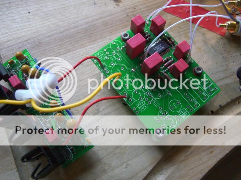
Sorry to hear of your woes. A couple of silly things first: can I check you've got a wire link installed at LK1? I can see solder but no wire - I'm assumnig it's underneath but just wanted to check. Also, have you fitted R5 and R10 (SMD feedback resistors underneath the board)?
TRs wouldn't be my first choice in this application, but they're not likely to oscillate and are solid regs. With TRs you shouldn't need the resistors at LK2 and LK3; the TRs are stable enough that you can use wire links.
The buzzing might be caused by a grounding problem. How did you hook up the 0V wires? The way I did it in the past was to bundle together the L/R signal 0V wires, the L/R 0V wires to each monoblock, and the 0V wires from each of the + and - regs, and twist them together before soldering that lot to a pin in the 0V hole (between the SMD decoupling caps on the AD815 board).
Basically the AD815 can get unstable if the 0V wires aren't commoned at the AD815's star. See page 10 of the datasheet for more information.
Good luck, let us know how you get on.
Cheers,
Carl
mikesnowdon
resU deretsigeR
Thanks for the pics Jon. I totally agree with Carls ideas above and would be surprised if those things he suggests dont fix it. Nice pot by the way
Hi Guys,
Thanks for the pointers! I tell you what, I wasn't smiling when I buzzed my ears off!!! Still, more fun than smelling burning flesh when soldering!
The link is there, as you suspected, Carl. And the feedback resistors are in place underneath. I measured them OK before they were installed (re-installed), but I will have another look tomorrow just to check I haven't knocked on off, or anything daft.
The earthing issue is interesting. I was able to transfer the fault from channel to channel, IIRC - it was the one amp that kicked off the trouble. I'll check the grounding tomorrow, but I'm sure that the grounds from input, output RCAs go and meet with the wire coming from centre star. BUT< and that's a bit BUT, the reg 0V I dobbed onto the 0V input pad for the power supply (having not fitted the on-board regs as you know). Also, I don't have a pin in the 0V star hole, just a wire coming out. I'll stick a pin in there and re-route the PSU grounds (and all the others, too) and see what happens.
Thanks again for the pointers!
Cheers, Mike! Yes, it's a beaut, isn't it?
Thanks for the pointers!
I tell you what, I wasn't smiling when I buzzed my ears off!!! Still, more fun than smelling burning flesh when soldering! The link is there, as you suspected, Carl. And the feedback resistors are in place underneath. I measured them OK before they were installed (re-installed), but I will have another look tomorrow just to check I haven't knocked on off, or anything daft.
The earthing issue is interesting. I was able to transfer the fault from channel to channel, IIRC - it was the one amp that kicked off the trouble. I'll check the grounding tomorrow, but I'm sure that the grounds from input, output RCAs go and meet with the wire coming from centre star. BUT< and that's a bit BUT, the reg 0V I dobbed onto the 0V input pad for the power supply (having not fitted the on-board regs as you know). Also, I don't have a pin in the 0V star hole, just a wire coming out. I'll stick a pin in there and re-route the PSU grounds (and all the others, too) and see what happens.
Thanks again for the pointers!
Cheers, Mike! Yes, it's a beaut, isn't it?
A quick update:
I've remade the 0V, using a central PCB pin and while I was there, I swapped out the film caps for the standard 'lytics and replaced the 1R network with a link.
Powers up fine and looks OK on the scope. The 815 gets only mildly warm. I'll try it in the system again tomorrow. In fact, I think I'll try it with a gash set of headphones and a headphone amp before it goes back onto the main rig. Without my head in the cans to begin with, for obvious reasons!
Another update:
Well, this has got me stumped! All was OK on the scope.
Into the main system again (didn't bother with setting up a headphone test). DAC into attenuator into pre into 2 x D290P (in mono).
One amp worked just fine (let's call it the "good" amp). The other, when connected causes trouble! This "bad" amp actually works just fine with all my other pre amps, so not anaccurate description, but it'll do for now.
I tried good amp on both left and right out on the pre = all fine. Therefore source is good on both channels and there was hardly any pop on switching.
Tried reconfiguring good amp into stereo, and on connecting both pre-out = trouble.
Tried connecting de-powered bad amp onto pre (without good amp connected) = trouble.
This "bad" amp sets off the pre for some reason. The "good" amp is fine on both channels of the pre. I tried both of the two different mono inputs on the bad amp, but I can't see how this could make any difference.
I didn't short the inputs when I was measuring DC offset, so I'll do this again. Likewise, I was thinking about dropping the nulling circuit into the board and seeing if that helps with anything.
I'll recheck my soldering, but can't see how this would make it work on one amp and not the other. Both D290Ps are similar age and have both been fully re-capped recently and run LME49710 op amps in the first stage.
Curiouser and curiouser...
Jon
Well, this has got me stumped!
All was OK on the scope.Into the main system again (didn't bother with setting up a headphone test). DAC into attenuator into pre into 2 x D290P (in mono).
One amp worked just fine (let's call it the "good" amp). The other, when connected causes trouble! This "bad" amp actually works just fine with all my other pre amps, so not anaccurate description, but it'll do for now.
I tried good amp on both left and right out on the pre = all fine. Therefore source is good on both channels and there was hardly any pop on switching.
Tried reconfiguring good amp into stereo, and on connecting both pre-out = trouble.
Tried connecting de-powered bad amp onto pre (without good amp connected) = trouble.
This "bad" amp sets off the pre for some reason. The "good" amp is fine on both channels of the pre. I tried both of the two different mono inputs on the bad amp, but I can't see how this could make any difference.
I didn't short the inputs when I was measuring DC offset, so I'll do this again. Likewise, I was thinking about dropping the nulling circuit into the board and seeing if that helps with anything.
I'll recheck my soldering, but can't see how this would make it work on one amp and not the other. Both D290Ps are similar age and have both been fully re-capped recently and run LME49710 op amps in the first stage.
Curiouser and curiouser...
Jon
Tried reconfiguring good amp into stereo, and on connecting both pre-out = trouble.
Do you mean that you can make it buzz by connecting the good power amp in a certain configuration?
Hi Carl,
In effect, yes. The good amp has a shorting link to make it mono and I bi-wire out of speakers 2 (L/R +-). So, I removed the shorting bar (unshort the input to stereo) and reconfigured my speakers so speakers 1 was treble L/R and set 2 was bass (classic bi-wire combination with these amps).
You're up early!
The buzzing might be caused by a grounding problem.l
Hi Carl,
You're too right it was. I've just finished populating the on-board power supplies and nulling circuit. Set the voltage to around 14.45V (240R/2K49). All looks good on the scope as usual!!
BUT < and that's a big but!! I remembered that I hadn't actually continuity tested the grounds. Why was it that the grounds on the input side of the pot weren't showing continuity? A run through the lashed up RCAs found the culprit! A ground-ring that wasn't seated properly.
All tightened up now and about to put it back in the main system. I'll recheck the ground continuity before I power up.Lesson learned!
Jon
Sadly, the problem is still there. I'll have to mull further....
I think I have some in a cupboard somewhere, yes. You can email me at [email protected], but be aware that the ad815 is now out of production and can be hard to source. I found one here: http://rover.ebay.com/rover/1/711-5...0001&campid=5338728743&icep_item=150466583001
Cheers,
Carl
Cheers,
Carl
This site contains affiliate links for which pink fish media may be compensated.
Was looking at the PCB images in post 174 on the PCB group buy thread:
http://pinkfishmedia.net/forum/showthread.php?t=33277&highlight=ad815&page=12
and comparing it to the original schematic on post 35 of the group build thread:
http://pinkfishmedia.net/forum/showthread.php?t=46481&page=3
If I'm not mistaken, I think that R5 and R10 (650R on the bottom of the board) should not connect to ground. If you look at R5 in the original schematic, you see that it connects between R4 (330R on top) and -IN1 on the AD815. So if I take out R4 and replace R5 with 560R to get unity gain, then R5 will still connect to ground and not to -IN1.
Let me know if I missed something.
Thanks,
Philippe