
You are using an out of date browser. It may not display this or other websites correctly.
You should upgrade or use an alternative browser.
You should upgrade or use an alternative browser.
AD815 preamp build thread
- Thread starter hacker
- Start date
Hi Guys,
The +ve reg is getting much hotter than the -ve reg. I've had another play this morning and measured the DC offset across the input. It was high. I think I might have been measuring the bias, but it's not as clear to me as my CK2III headphone amp. Suffice to say that with the trimmers tweaked, and the DC set to around 1mV, the +ve rail reg is much cooler - so much so that I can now hold my finger on the sink continuously. I changed the vpltage setting resistors to 2K69 from 3K3 (nearest I had in stock) and I'm running a steady +-15.6V.
Using my small (Velleman) sig gen, I can see the sine on my scope on the input, but would appreciate a pointer as to where to check for output, as I wasn't getting any sine out of either side of the AD815, but I know it works on at least one channel.
I'll solder the 10K pot back into the circuit and see what the measurements are then.
Many thanks
Jon
Fretless Eric
Musketeer Bathos
Carl, the bits arrived. Thanks a lot for your work. I need to go back through the threads and check them off now.
Edit, please move this to the group buy thread, I think this is where all the acknowledgments of delivery are collated.
Edit, please move this to the group buy thread, I think this is where all the acknowledgments of delivery are collated.
I've been giving thought to optimising the preamp's PSU and bypass caps, but my knowledge of such things is a glass ceiling for me so I'm turning to the PFM collective for answers.
Bypassing is currently handled by an SMD 0.1uF C0G ceramic cap right at the AD815's pins, plus a 68uF electrolytic. I'd love to get rid of the elcaps entirely, and substitute a 10u or 22u Wima MKS2-XL. Is the amp going to remain stable with a film cap on it's PSU pins? Is it a good idea, and why (not)?
For the upstream PSU, I spent a few hours today building a simple +/-35V supply from an Avondale 25-0-25 EI-core trafo with both secondaries paralleled. It's rectified by 4 HFA25TB60PBF hexfred diodes and smoothed by 2 10,000uF Kendeil caps. This gives me a high quality, low impedance raw supply. The question that I keep asking myself is about regulators... ALWSRs or TeddyRegs? The teddyregs are going to mop up more noise with the highly effective RC filter/cap multiplier type arrangements, but this will come at the cost of higher output impedance. The ALWSRs on the other hand will provide a super low output impedance supply, but won't mop up as much HF crap as the teddyregs.
I'm probably gonna try both and see what I fancy, but what about the theory? I'm interested in what, in this application, will be the biggest deciding factors. Does the AD815 have a constant current draw, making it more immune to regulator output impedance, or is it likely to have dynamic voltage swings that will be better served by a fast regulator?
Opinions, formulae, speculation... all are welcome.
Carl
I haven't tried those, no. They're rather expensive and I've got a bits box full of goodies, so I thought I'd use what I've got. Having said that, I've only ever heard good things about the 4-poles and may try them one day - plus if Andy reckons they're good, then I'm very willing to listen.
laverda
pfm Member
I haven't tried those, no. They're rather expensive and I've got a bits box full of goodies, so I thought I'd use what I've got. Having said that, I've only ever heard good things about the 4-poles and may try them one day - plus if Andy reckons they're good, then I'm very willing to listen.
4 pole caps (BHC or Jensen) are and have been one of the best upgrades to my system/s (in almost all applications) They work especially well with sregs and add somthing special to power amps. In a split rail setup you do need two, unless you opt for a good duel DC to DC converter, whereby you need just a single rail supply and the converter manufactures a (neg) -dcv rail...
")
Expensive.........depends on how one looks at it. If your going to be buying quality (standard) caps anyway 10-15 or even 20ukp is not uncommon for this size of 10000uf 63v, so why not give 4 poles a go.
They run at about 25UKP a piece, (I believe Patrick Dixon http://www.at-tunes.co.uk/ can supply keen PFMers) and worth every penny, a audiofile bargain IMO, but I have noticed a reluctance for PFM DIYers to sercome to this huge outlay. I'm sure, their not too sure if this investment will be worth it........
Graham
PigletsDad
My intelligence test came back negative.
Film cap as PSU bypass may give problems depending on what regulator is feeding it.
As far as I know, a film cap across the main reservoir caps cannot do any harm, but may do some good. After the regulator, there is a risk of resonances or even oscillation - the regulator output looks exactly like an inductance (for most types), so that when connected to a high Q low-loss film, you will get a resonance. To avoid trouble, you need to add a small resistor in series - say 0.22Ohm would be good.
Electrolytics have exactly this sort of ESR, which is why they work so well in this position.
MarkW
Full Speed & Pagan
4 pole caps (BHC or Jensen) are and have been one of the best upgrades to my system/s (in almost all applications) They work especially well with sregs and add somthing special to power amps. In a split rail setup you do need two, unless you opt for a good duel DC to DC converter, whereby you need just a single rail supply and the converter manufactures a (neg) -dcv rail...
Expensive.........depends on how one looks at it. If your going to be buying quality (standard) caps anyway 10-15 or even 20ukp is not uncommon for this size of 10000uf 63v, so why not give 4 poles a go.
They run at about 25UKP a piece, (I believe Patrick Dixon http://www.at-tunes.co.uk/ can supply keen PFMers) and worth every penny, a audiofile bargain IMO, but I have noticed a reluctance for PFM DIYers to sercome to this huge outlay. I'm sure, their not too sure if this investment will be worth it........
Graham
Graham
I can second the recommendation. My dual mono Hypex power amp uses a T-Net cap on each rail and it was a big upgrade. As you say, the price is a bit of a hurdle, but jump that and you'll find it's worth the effort.
Mark
Hi,
Well, I think I have isolated the fault. My sig gen outputs a steady 110mVAC, and I could easily trace that to Pin 9 ( +IN1 = LH Input) on the AD815. The RH input was traceable all the way to C8, without the cap in. Once the sockets were linked (or the cap replaced) the signal disappeared. All the other continuity testing was fine, apart from........ it seems that Pins 13 (+Vs) and Pin 16 (+IN2 = RH Input) are connected!!! The continuity tester shows them linked, but I'm baffled as to how, unless it is a faulty AD815. This would explain the high current draw on the +ve rail, I believe.
I'll check there is no bridging between the heat tabs (already connected to the +ve rail as per the datasheet) and Pin 16.
Cheers
Jon
Well, I think I have isolated the fault. My sig gen outputs a steady 110mVAC, and I could easily trace that to Pin 9 ( +IN1 = LH Input) on the AD815. The RH input was traceable all the way to C8, without the cap in. Once the sockets were linked (or the cap replaced) the signal disappeared. All the other continuity testing was fine, apart from........ it seems that Pins 13 (+Vs) and Pin 16 (+IN2 = RH Input) are connected!!!
The continuity tester shows them linked, but I'm baffled as to how, unless it is a faulty AD815. This would explain the high current draw on the +ve rail, I believe.I'll check there is no bridging between the heat tabs (already connected to the +ve rail as per the datasheet) and Pin 16.
Cheers
Jon
Hi Everyone,
I've fired up my amp, using the onboard PSU, and I've only got one live channel. I'll have a play around with the meter and scope to see what's what, but I was wondering if anyone else was had hot heatsinks on the +ve rail? Both on my Pass D1 +-30VDC PSU and the onboard PSU +ve reg sinks are very hot (using slide-on sinks).
Fatmarley
"It appears my intelligence circuits have melted"
Finally got a chance to finish the AD815 preamp today. I'm running it with the standard regs but with 4-pole caps in the psu.
Measured dc, and i get around -65mv whatever way i turn the pots. I gave up in the end and plugged it into the system. . .
Wow, this sounds really good! and knowing how RN60's plus new caps sound from new, this is obviously, only going to get better. Bass is deep, punchy and very well controlled. Mid is really nice and treble really detailed but smooth.
Thank's very much Carl (and Carlos fm)
Hi Jon,
Have you checked that the lower pad of the SMD resistor R9 isn't bridged to pin 13? That would cause the effect you're experiencing. Same for a bridge between pins 13 and 14.
Other than that, it may be that you have a duff opamp
Good luck with it, and post some pictures when you can.
Cheers,
Carl
Have you checked that the lower pad of the SMD resistor R9 isn't bridged to pin 13? That would cause the effect you're experiencing. Same for a bridge between pins 13 and 14.
Other than that, it may be that you have a duff opamp
Good luck with it, and post some pictures when you can.
Cheers,
Carl
Matt, that's great news People seem to be having trouble with the DC nulling circuit, so I think I'll have a go at debugging it sometime soon. I have to confess that my motivation to do it isn't that great, because I've got one of Jos van Eindhoven's passive remove attenuators and it's ok to have DC across it, meaning no DC nulling or coupling caps for me, just source+output coupling cap / ad815 / power+input coupling cap
Glad to hear it's working for you. What's your normal pre, and how does the ad815 compare?
People seem to be having trouble with the DC nulling circuit, so I think I'll have a go at debugging it sometime soon. I have to confess that my motivation to do it isn't that great, because I've got one of Jos van Eindhoven's passive remove attenuators and it's ok to have DC across it, meaning no DC nulling or coupling caps for me, just source+output coupling cap / ad815 / power+input coupling cap Glad to hear it's working for you. What's your normal pre, and how does the ad815 compare?
Fatmarley
"It appears my intelligence circuits have melted"
My normal pre is the starfish but it's not traco'd, so i don't think it would be fair for me to comment.
I'm using a vishay dale, stepped attenuator in my AD815. Do you think i should just remove the nulling circuit? I'm not sure why i hooked it up in the first place, to be honest. I knew it wouldn't damage the pot, but thought it may have somehow improved the sound?
I'm using a vishay dale, stepped attenuator in my AD815. Do you think i should just remove the nulling circuit? I'm not sure why i hooked it up in the first place, to be honest. I knew it wouldn't damage the pot, but thought it may have somehow improved the sound?
Of course it's fair to comment! You're comparing a non-optimal AD815 to a non-optimal Starfish, so that's fair game I reckon
I dunno about your pot; I wouldn't want to say. I checked with Jos before hooking it up without caps or nulling circuitry. It's getting there... pics soon.
I dunno about your pot; I wouldn't want to say. I checked with Jos before hooking it up without caps or nulling circuitry. It's getting there... pics soon.
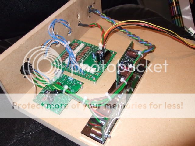
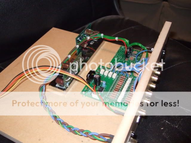
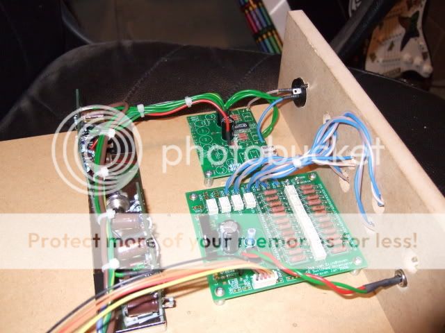
The build so far:
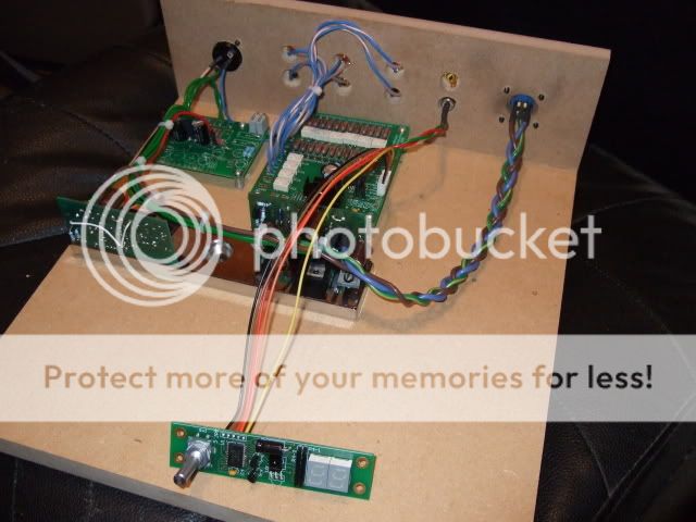
The empty space on the right is reserved for a Monica2 DAC and accompanying ALWSR and Flea. I decided to go for a built-in DAC, rather than have it located externally. The connector with the brown/blue/green braided wires is a 7-pole locking type that I bought a couple of years ago from RS. It'll be hooked up to an off-board PSU containing a couple of raw DC supplies, one for the AD815 and one for the Monica2.
The AD815 supply is already built and consists of an Avondale 25-0-25 EI core with paralleled secondaries, HEXFRED rectifiers, and 10000u Kendeil capacitors that provides a good clean +/-35VDC for the AD815. Inside the preamp you can see 2 ALWSRs bolted to a huge chunk of metal that does duty as a heatsink; the SR pre-regs were getting hot because they're dropping 20V each to give a stable +/-15V to the AD815 board.
If you look carefully you'll see the DC nulling circuit isn't fully populated. That's because I won't be using it. The Monica2 has BlackGate output coupling caps, and the monoblocks will have input coupling caps. Jos van Eindhoven (the created of the remote attenuator circuit) assures me that some DC across the attenuator is not a problem, which means I can do away with almost all of the coupling caps and have only 3 in the entire signal chain: BGs in the DAC, MKS2-XLs in the monoblocks, and Mundorf Silver/Oil in the speaker crossovers. That should make a huge difference from my old Naim-style rig that had 8 coupling caps per channel! (2 in the CD3.5, 4 in the preamp, 1 in the power amp, 1 in the speaker).
The Monica2 will have a custom power supply. The 80MHz clock will be powered from a dedicated Flea reg with it's own trafo winding, rectifier, smoothing caps etc. The rest of the board will get 12V from a FET-VBE'd ALWSR. The exception will be the DAC chip itself, which I plan to power from a Flea running off the ALWSR supply.
Anyway, the inner part of the preamp is made of MDF, as you can see. 3/4" for the base, 1/2" for the rear panel. The PCBs are supported on 10mm high clear rubber tubing that's screwed to the base with thin screws. At the moment the base is 12" x 12", but I plan on reducing the depth and hopefully getting it down to 12" x 7.41" (the golden ratio).
The front panel is going to be made from MDF and clad in leather, just like my Ergos. I'll have a rectangular hole cut in there for the digital display window, and I'll fit a piece of smoked acrylic in it.
I'm going to create an outer sleeve for it, and the whole design will be very much like a Naim shoebox, except the outer will be a Sapele box. This should complete the look and create a nice matching box to go with the speakers. I'll build up a pair of monoblocks in the same style.
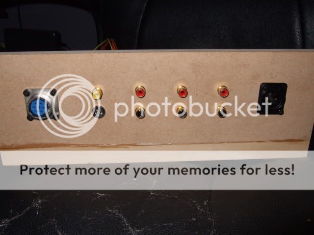
The rear panel accommodates the 7-pole power connector, an RCA connector for the DAC digital input, a wallwart jack for the remote-controlled attenuator board, and 3 other inputs. The XLR connector on the right is the pre-amp output and will be used to hook the pre up to the monoblocks. You can see I've not yet sanded and tidied the back panel up...
Lots of progress made, but lots still to do
Carl
The empty space on the right is reserved for a Monica2 DAC and accompanying ALWSR and Flea. I decided to go for a built-in DAC, rather than have it located externally. The connector with the brown/blue/green braided wires is a 7-pole locking type that I bought a couple of years ago from RS. It'll be hooked up to an off-board PSU containing a couple of raw DC supplies, one for the AD815 and one for the Monica2.
The AD815 supply is already built and consists of an Avondale 25-0-25 EI core with paralleled secondaries, HEXFRED rectifiers, and 10000u Kendeil capacitors that provides a good clean +/-35VDC for the AD815. Inside the preamp you can see 2 ALWSRs bolted to a huge chunk of metal that does duty as a heatsink; the SR pre-regs were getting hot because they're dropping 20V each to give a stable +/-15V to the AD815 board.
If you look carefully you'll see the DC nulling circuit isn't fully populated. That's because I won't be using it. The Monica2 has BlackGate output coupling caps, and the monoblocks will have input coupling caps. Jos van Eindhoven (the created of the remote attenuator circuit) assures me that some DC across the attenuator is not a problem, which means I can do away with almost all of the coupling caps and have only 3 in the entire signal chain: BGs in the DAC, MKS2-XLs in the monoblocks, and Mundorf Silver/Oil in the speaker crossovers. That should make a huge difference from my old Naim-style rig that had 8 coupling caps per channel! (2 in the CD3.5, 4 in the preamp, 1 in the power amp, 1 in the speaker).
The Monica2 will have a custom power supply. The 80MHz clock will be powered from a dedicated Flea reg with it's own trafo winding, rectifier, smoothing caps etc. The rest of the board will get 12V from a FET-VBE'd ALWSR. The exception will be the DAC chip itself, which I plan to power from a Flea running off the ALWSR supply.
Anyway, the inner part of the preamp is made of MDF, as you can see. 3/4" for the base, 1/2" for the rear panel. The PCBs are supported on 10mm high clear rubber tubing that's screwed to the base with thin screws. At the moment the base is 12" x 12", but I plan on reducing the depth and hopefully getting it down to 12" x 7.41" (the golden ratio).
The front panel is going to be made from MDF and clad in leather, just like my Ergos. I'll have a rectangular hole cut in there for the digital display window, and I'll fit a piece of smoked acrylic in it.
I'm going to create an outer sleeve for it, and the whole design will be very much like a Naim shoebox, except the outer will be a Sapele box. This should complete the look and create a nice matching box to go with the speakers. I'll build up a pair of monoblocks in the same style.
The rear panel accommodates the 7-pole power connector, an RCA connector for the DAC digital input, a wallwart jack for the remote-controlled attenuator board, and 3 other inputs. The XLR connector on the right is the pre-amp output and will be used to hook the pre up to the monoblocks. You can see I've not yet sanded and tidied the back panel up...
Lots of progress made, but lots still to do
Carl
MarkW
Full Speed & Pagan
Carl
That's looking nice. Very neat and well put together. Jos' attenuator is a quality item. I have mine in the Starfish and it works a treat (though I did have to move the input switching relays off board).
I am sure we all look forward to the listening report once its done.
Mark
That's looking nice. Very neat and well put together. Jos' attenuator is a quality item. I have mine in the Starfish and it works a treat (though I did have to move the input switching relays off board).
I am sure we all look forward to the listening report once its done.
Mark