
You are using an out of date browser. It may not display this or other websites correctly.
You should upgrade or use an alternative browser.
You should upgrade or use an alternative browser.
Speakers: MUN17-3W
- Thread starter fraser.
- Start date
Maybe I'm overthinking this... if the rear baffle is removable could I not just fit the woofer with nuts and bolts + washer...
I just realised carrotman said exactly this a few pages back!
Is there a reason that's not done often? I think I've seen it on BBC type speakers but that's about it.
I just realised carrotman said exactly this a few pages back!
Is there a reason that's not done often? I think I've seen it on BBC type speakers but that's about it.
Last edited:
James
Lord of the Erg\o/s
My technique for drilling bolt holes and installing T-nuts entails:... if you use t nuts make sure the holes for them are at 90 degrees, hard to do
with a hand drill.Tighten them in by using a big washer on the driver side, don't hammer them in if you crossovethread them their a pain in the arse.
- Position the driver in the desired location on the baffle.
- Hand-drill the first 2-3mm of the holes with a drill bit of the same size as the fastener (6mm in this case), taking care not to shift the driver's location.
- Remove the driver and finish drilling the holes with a drill-press to ensure perpendicularity.
- Flip the baffle and use a stepped bit to increase the size of the hole so it is just wide and deep enough to accommodate the T-nut on the reverse side.
- Thread the M6 fastener with a flat washer into the hole and T-nut, and tighten thereby pulling the T-nut into the back of the baffle.
- Before it is fully seated, apply some adhesive to the T-nut - making sure to avoid the threaded area - so it is secured to the baffle and straight to avoid cross-threading or popping it out.
James
Lord of the Erg\o/s
You could, but bear in mind unattached steel nuts and washers will be strongly attracted to the woofer's magnet.Maybe I'm overthinking this... if the rear baffle is removable could I not just fit the woofer with nuts and bolts + washer...
Is there a reason that's not done often? I think I've seen it on BBC type speakers but that's about it.
That's great info, thanks for taking the time to detail that. I'm still mulling over the risk / reward of the mounting. Perhaps I will attempt threaded inserts on the rear baffle first and see how it goes.
Next steps
Sort out the bass driver rebate / finish front baffle
Finish bass cabinets
Order the sockets / connection
Make some kind of rack to site the amps on / practice my router skills
Figure out how I'm going to make the upper cabinets...
Next steps
Sort out the bass driver rebate / finish front baffle
Finish bass cabinets
Order the sockets / connection
Make some kind of rack to site the amps on / practice my router skills
Figure out how I'm going to make the upper cabinets...
It has been slow progress in the last couple of weeks, mainly due to a back injury which has thankfully almost cleared up.
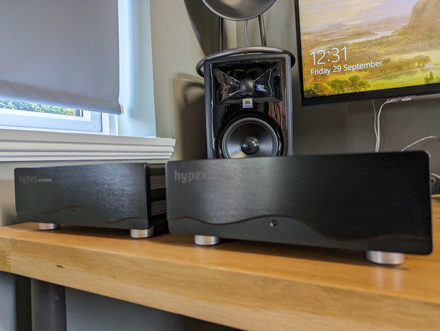
The rear baffles have now been re-cut, this time in valchromat and with a slightly larger cut out for ventilation across top and bottom holes.

Next up i'll measure out the connections, get the holes cut for those, and attempt to rebate the hypex with my new favourite toy.
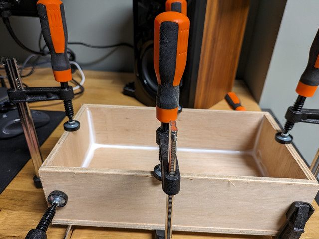
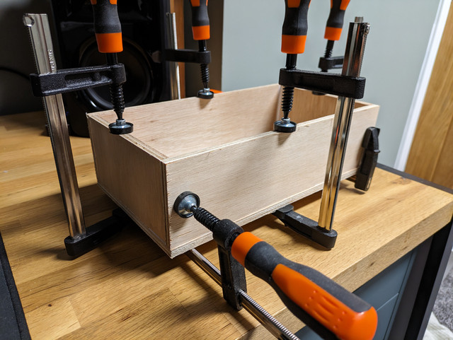
The only other progress was on the mini-cabinets to seal the hypex units against the rear baffle. These have been lovingly crafted in 6mm ply and i'll glue these onto the baffle after some test fitting. There will only be one small hole to drill to carry the leads from the amp to the woofer; the rest of the wiring can be routed through the main cabinet.
The rear baffles have now been re-cut, this time in valchromat and with a slightly larger cut out for ventilation across top and bottom holes.
Next up i'll measure out the connections, get the holes cut for those, and attempt to rebate the hypex with my new favourite toy.
The only other progress was on the mini-cabinets to seal the hypex units against the rear baffle. These have been lovingly crafted in 6mm ply and i'll glue these onto the baffle after some test fitting. There will only be one small hole to drill to carry the leads from the amp to the woofer; the rest of the wiring can be routed through the main cabinet.
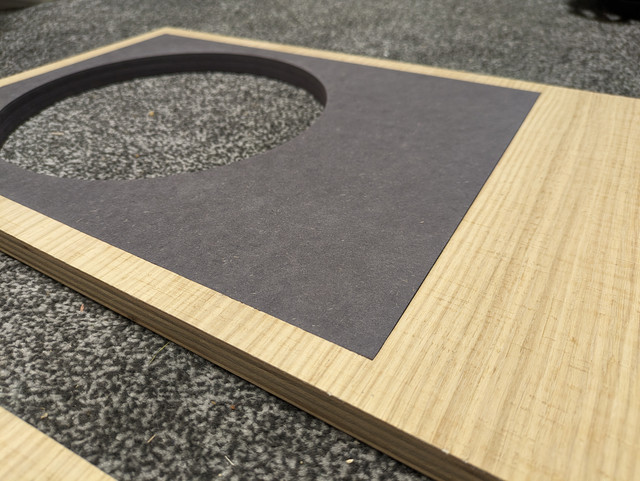
Today I test fitted the front baffle inlays, which involved a bit of sanding and a little work with a blade to sharpen the corners in the ply which were rounded on the inner corners of the cut out.
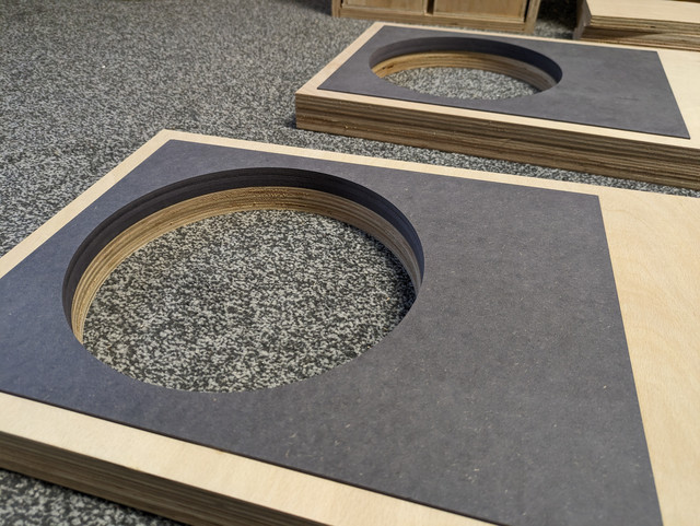
There's a depth variance of 1mm which in theory is roughly the same as the veneer. In reality this looks a little more so I may end applying veneer to front and back of the ply to get everything flush.
I'm a bit unclear on the order of events here... Is best practice to veneer before routing / cutting? Generally when I've done this before I've just veneered everything last but that's not going to work here due to the complexity of the cabinets.
James post here is most important!My technique for drilling bolt holes and installing T-nuts entails:
A similar technique could be used for threaded inserts. The key is getting them perfectly aligned thread wise.
- Position the driver in the desired location on the baffle.
- Hand-drill the first 2-3mm of the holes with a drill bit of the same size as the fastener (6mm in this case), taking care not to shift the driver's location.
- Remove the driver and finish drilling the holes with a drill-press to ensure perpendicularity.
- Flip the baffle and use a stepped bit to increase the size of the hole so it is just wide and deep enough to accommodate the T-nut on the reverse side.
- Thread the M6 fastener with a flat washer into the hole and T-nut, and tighten thereby pulling the T-nut into the back of the baffle.
- Before it is fully seated, apply some adhesive to the T-nut - making sure to avoid the threaded area - so it is secured to the baffle and straight to avoid cross-threading or popping it out.
Getting a hole off centre or slightly inebriated going in is a major pain in the arse!!
T nuts MUST be glued, they can knock out with just the weight of a bolt and if they come loose while trying to remove a bolt, pray you have access to the rear!
Lovely build btw, looking forward to seeing them complete!
EDIT: Stainless steel nuts bolts washers?
a.palfreyman
pfm Member
I know that feeling all too well.it would look like someone had grated a tree
Good stuff, keep it up.
")
Thanks chaps, and I agree James' post is great guidance if I go down this route!
I'm away with the family sunning myself by a pool so there won't be much progress for the next few weeks. We left on the first day of storm babet so were lucky to miss the worst if it and get to the airport (Edinburgh) in time!
I should say a public thankyou to Dave @S-Man for offering to put the crossovers together for me. This will be a massive help where I have very little experience. If it was a simpler 'upgrade' or using a PCB I might have taken it on but I'm a complete novice with point to point wiring.
I tried out the router today. I wish I'd bought one ages ago... It would have been so handy for so many previous projects and the finish is far better than the other cutting tools I've used.
The first task was to tidy up the hypex enclosures, where there was some material to trim off on the long edges, between 1-2mm. I previously would have done this with a sander, with mixed results and a lot of effort. I used the worktop router bit to level them off in seconds and the finish is more or less perfect, just a finish sanding needed.
The sensible thing to do would have been to practice on some scrap material next before attempting anything difficult, but I skipped this stage and went straight to rebating the hypex. I'd be interested to here what the 'correct' way of doing this would be, as I'm pretty sure what I did is not correct...
a) Placed the router bit cutting edge where I want to make a cut
b) use a square to level this across the board
c) clamp something flat along this line as a guide
d) set the router depth to match the rebate needed
e) run the router across the guide
f) repeat across each side
The end result is... just about acceptable.
Will add some pics later
This week I veneered the internal face of the front baffle which will be glued to another sheet of ply to make a total baffle depth of circa 50mm. The purpose of this layer of veneer (and probably the next one) is to increase the depth of the outward face of the baffle to bring it up level with the valchromat material which houses the bass driver.


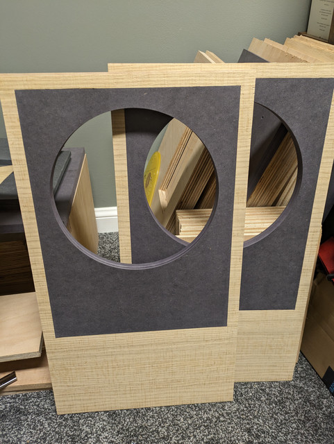
There's still around 2mm protruding on the outer face, so I'll add a double layer of veneer to the front and that should bring it up perfectly level with the valchromat.
There's still around 2mm protruding on the outer face, so I'll add a double layer of veneer to the front and that should bring it up perfectly level with the valchromat.
a.palfreyman
pfm Member
Funnily enough I quite like the horiz grain...
The veneer I'm using, nice as it is, isn't very figured... In the sale at wood veneer hub I noticed they have some nice pippy oak construction (2mm) veneer so I bought some of that to see if I like it better.
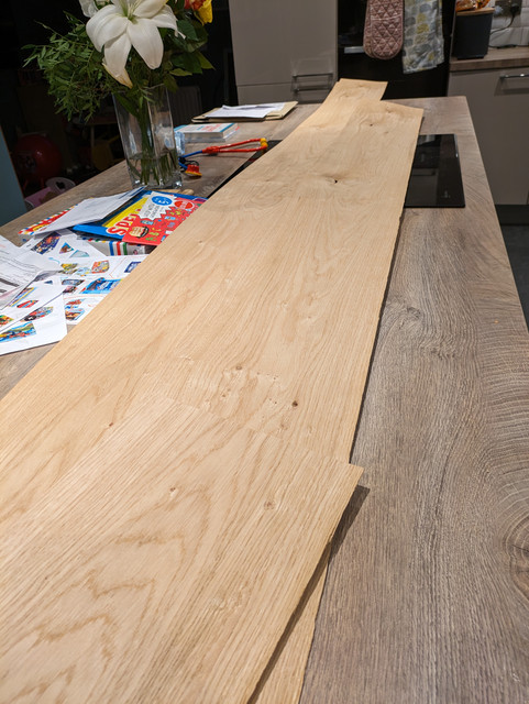
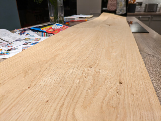
This stuff looks lovely. If I have enough I'll use it all around. If not another build will benefit from it.
This stuff looks lovely. If I have enough I'll use it all around. If not another build will benefit from it.
These have stalled a bit. You may have noticed that every picture is taken in a room not suitable for messy / noisy woodworking... therefore i've decided to prioritise setting up a workshop in the garage before tackling the trickier bits of this build. Everything to date has been done on a couple of those little steps you see in ikea, with a bit of chipboard on top. Not ideal!
This is what i have to work with:
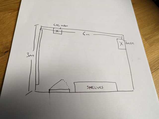
I'd rather not move the racking if i can help it as it's a bit of a pain to unbolt and secure elsewhere
current state of affairs:

materials available:
spare 3m worktop, think it's beech or maybe oak
about 20m2 of ply / OSB
softwood batons, about 10; about 2x4
I was thinking about having the short side (At the back) as the working area but i'm conscious that any work needed on the boiler, or potentially a replacement (it's about 18 years old I believe) may mean ripping bits out.
This is what i have to work with:
I'd rather not move the racking if i can help it as it's a bit of a pain to unbolt and secure elsewhere
current state of affairs:
materials available:
spare 3m worktop, think it's beech or maybe oak
about 20m2 of ply / OSB
softwood batons, about 10; about 2x4
I was thinking about having the short side (At the back) as the working area but i'm conscious that any work needed on the boiler, or potentially a replacement (it's about 18 years old I believe) may mean ripping bits out.