advertisement


Flea and other mods to CDi...

OK, so I literally dusted off scope tonight for a look - 4 channel Fluke driven by an imbecil :) Flea oscillator is running, but is it supposed to look like this?

24724760689_7d965e829d_b.jpg


I just pressed auto-set :) 5v out from reg on Flea OK, so I assume normal, and just looks horrible?

Thanks, Richard
 
No that's pretty much what you'll see.
The ripples top and bottom are artifacts of the way it interacts with the load (and, especially, your measurement of it - 10pF from the probe really, really doesnt help!); what makes it 'good' is the bit a scope won't show - the exactitude of the time between transistions ;)

Remember the top and bottom ripples don't much matter - they are an (mostly measurement) artifact way beyond the logic switching levels = both in the saturation region beyond 'on' and 'off'.
 
Thanks Martin- understood, start and stop is more important than smoothness, just wanted to rule it out :)

I have a new laser arriving soon, next step is to fit it and leave servo board measureable - I kind of hope it is not laser (after only 7 years since last replacement), but maybe easier if it is :)

Weird thing for me is I was listening when it failed...no skipping, it just stopped and threw an ERR on display. We'll see - Micromega sounding good, but I'm missing some things....

Edited to add: you should see waveform when I switch off main power (Flea still powered) :)
 
Edit to add: if it makes you feel better, here's the last time I took a pic of a flea output with a little finesse, i.e. what you might expect to get. I can't remember who for but recall it was driving a CD3.5 so at 16.934Mhz. Probe was a bit of 50ohm coax and some termination resistors (1K series in the 3.5 inverter input/50ohm input termination at the scope = 21:1 diy probe soldered in place; Tek 475A)

DSCF1893_800px.jpg


(eek! this image is dated March 2006!)
 
LOL :) Thanks - yours is better smoothed than mine...but mine is just a 10:1 probe.
 
Reality is this: what little overshoot my old trace shows is well-damped and way out at c.150Mhz. Not the end of the world...
 
No, understood, thanks Martin - as long as start and stop is there, and it is (I assume very accurately), then I have no concern given me loading the cct with a probe. I just wanted to make sure it was not the bastard cause of my CDI no longer reading discs :)
 
I do hope that comes down to something simple and fixable. Finding it though, that's the trick... esp since you've already worked-over the usu suspects such as electrolytic caps on the transport board :/
 
OK - it is clearly going to be a bastard...new (2nd hand - suspect, poor packaging, abused ribbon, and fecking expensive) laser fitted, same symptoms.

Time for some deeper fault finding - photos below as much for my reference as anything else.

Stay tuned...photos;

Servo PCB - based on TDA8808 and 8809 chips, so I am hopeful the Marantz service manual I have (and uses same) will give some clues;

25145310405_d16167f394_b.jpg

25145314895_ceeae9c69e_b.jpg

25052033401_2999a98b63_b.jpg


The 2 CDM9 based mechs side by side - apart from the fancier finish of the PRO, the only difference is the spin motor;

24777629079_a43bfe3a3e_b.jpg


Transplant process pretty straightforward - remove the retainer holding laser ribbon cable in place (a tight fit because of the bigger motor housing on the PRO), undo the 2 small allen screws, remove laser assemble. All very carefully of course - and watch for the small ball bearings top and bottom. They're normal locked in place as the little grease used on them hardens up - i removed, cleaned and used a drop of oil this time...fat lot of good it did :)

24514646464_853140c9bf_b.jpg

24518479843_6e97d2f194_b.jpg

24849684310_dc9c8848d7_b.jpg

25119001176_f157306b33_b.jpg

25052066131_6b7a918362_b.jpg

25145380475_88bddf9a92_b.jpg


Richard
 
Actually, scrub that - new laser displays slightly different fault, in that disc sometimes gently runs backward (1 in 3 TOC attempts). Given state the mech arrived to me in, I'm going to return it as faulty.

Am just refitting original, but will check all tants on servo board first.
 
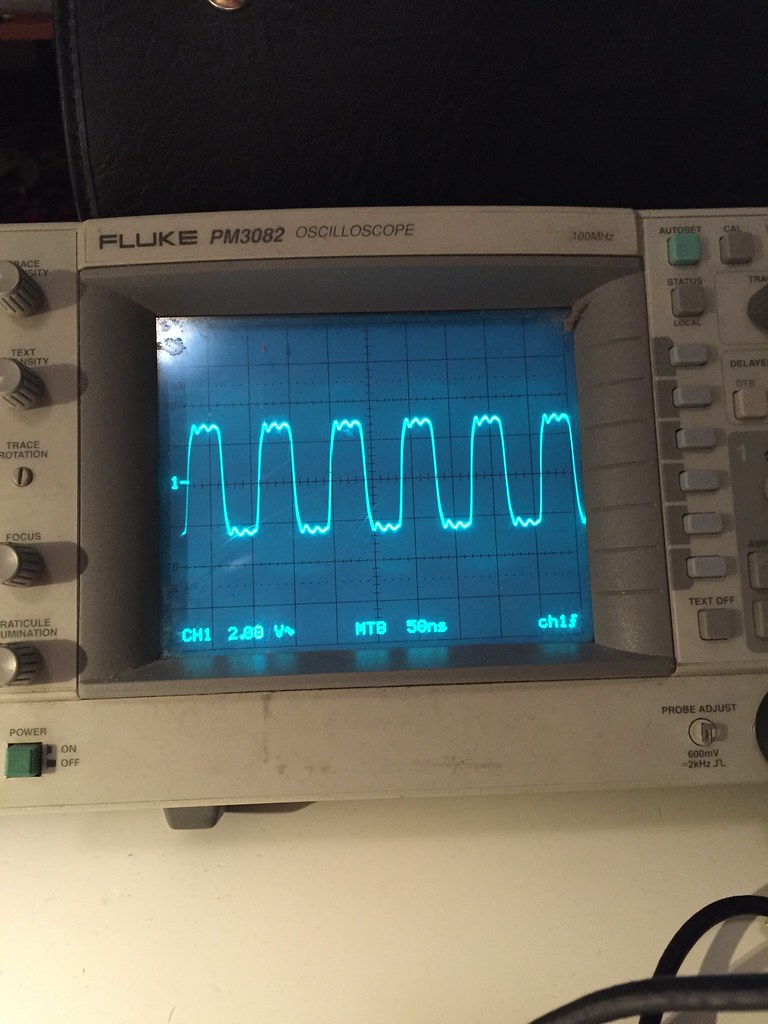
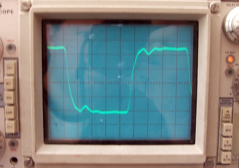
Refitting original laser returns fault to original. Two short spin motor pulses as it tries to read TOC, with stop/play LEDs flashing in sync (and main display goinging off when the stop or play LED is lit). Behaviour exactly same either with or without disc inserted.

I've checked all voltages and signals on the servo board as it tries to read TOC - and to my completely untrained eye/knowledge (I was never much good at this when I was paid for it - 30 years in technology have not helped :)) all looks OK. Supply lines at all relevant pins on the 8808 and 8809, driver opamps same. Signal lines rise and fall in time with the motor pulses/laser focus attempts.

At this stage I have to rule out the laser itself and get a known good CDM 9 before going any further - for all I know I just swapped a poor laser for an even sicker one...

So, off to setup some eBay searches :)
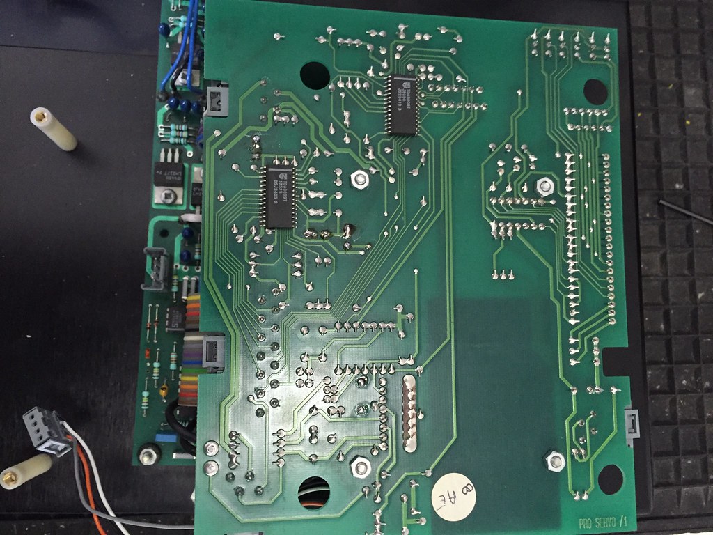
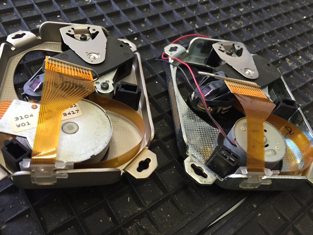
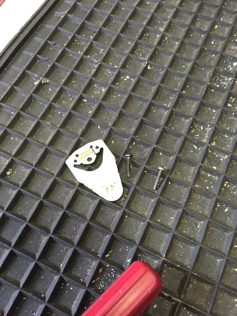
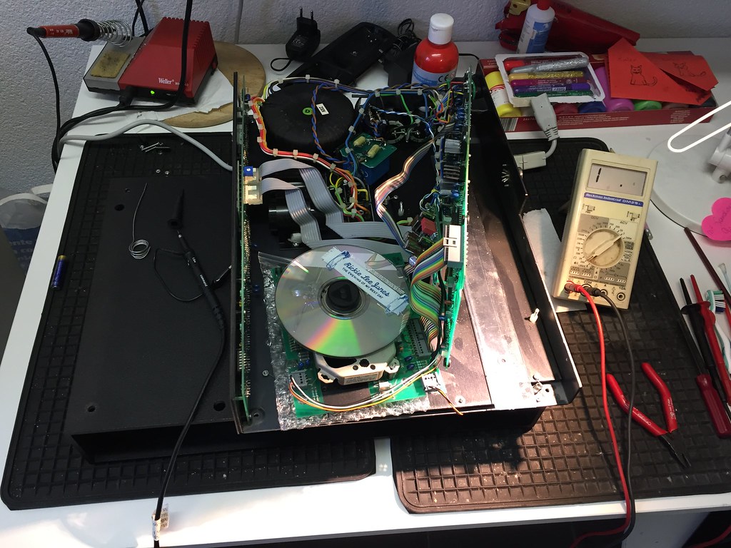
Some photos;

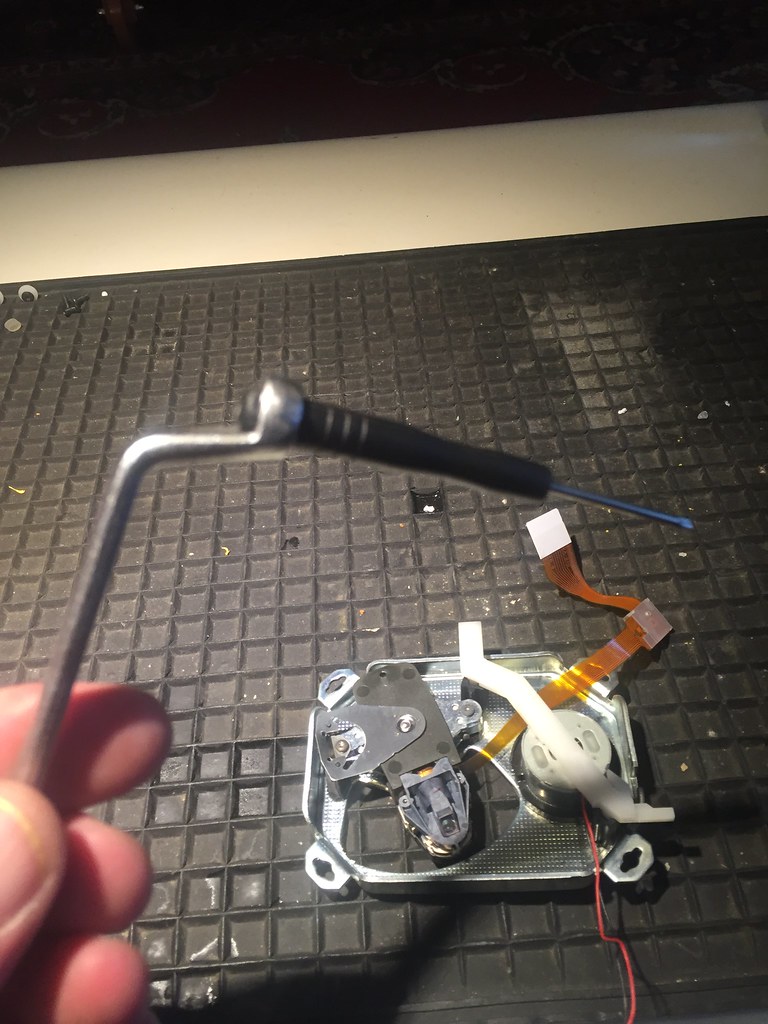
Just able to work on it - either with main PCB mounted and mech flipped vertically, or like this;

24522812043_6108f02cf9_b.jpg


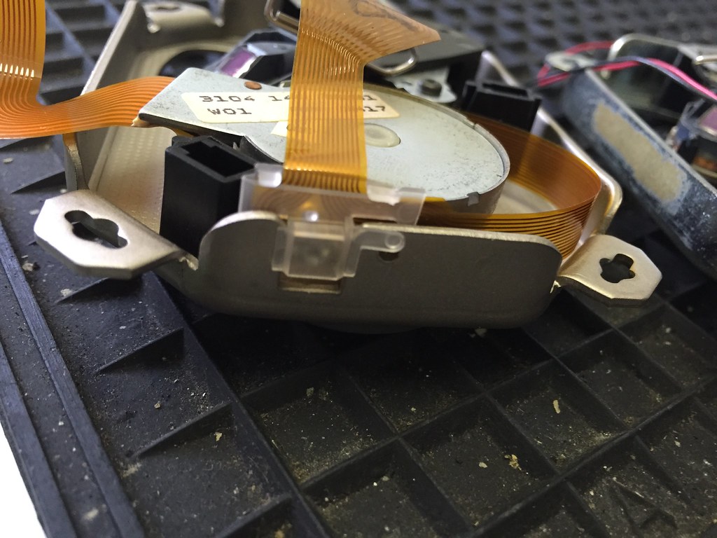
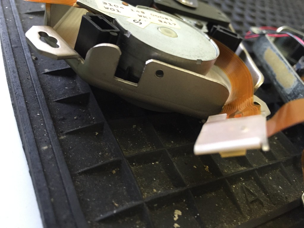
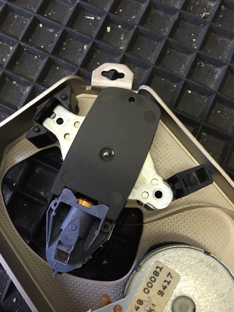
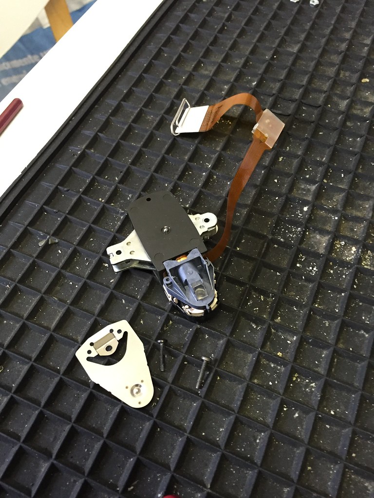
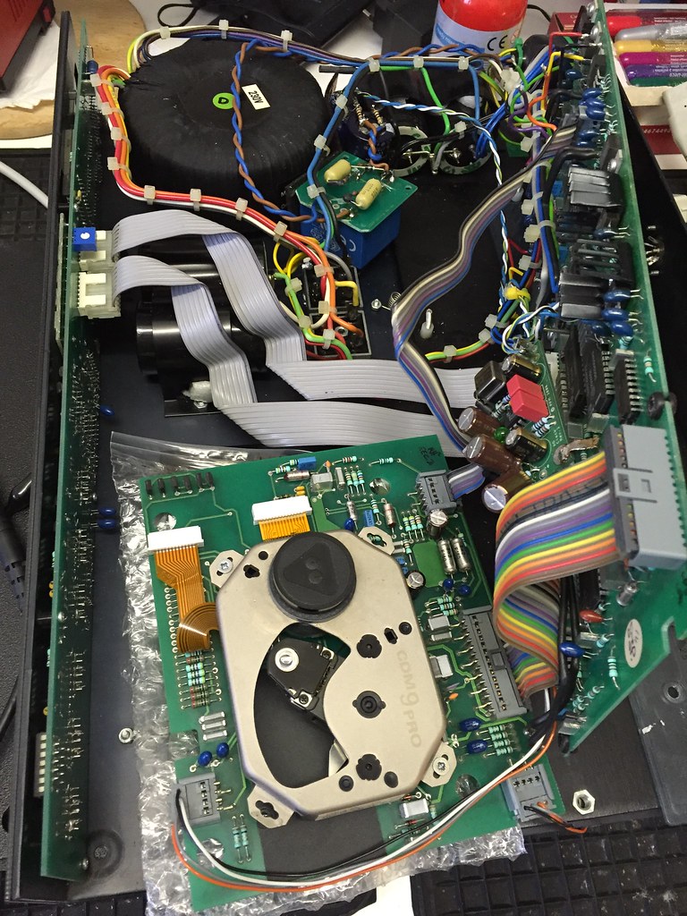
Minimalist mounting to give maximum access;

24782014639_ea03d6147b_b.jpg


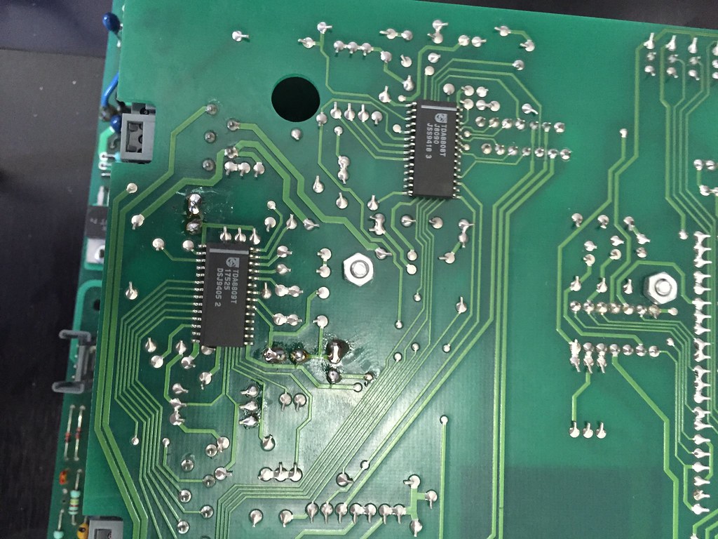
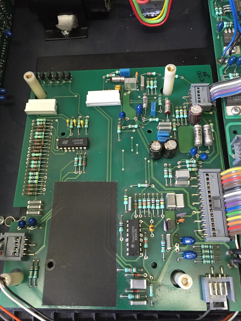
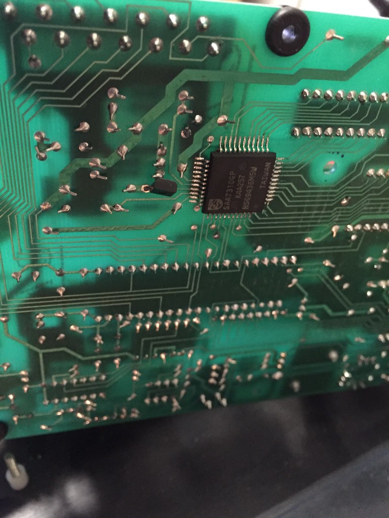
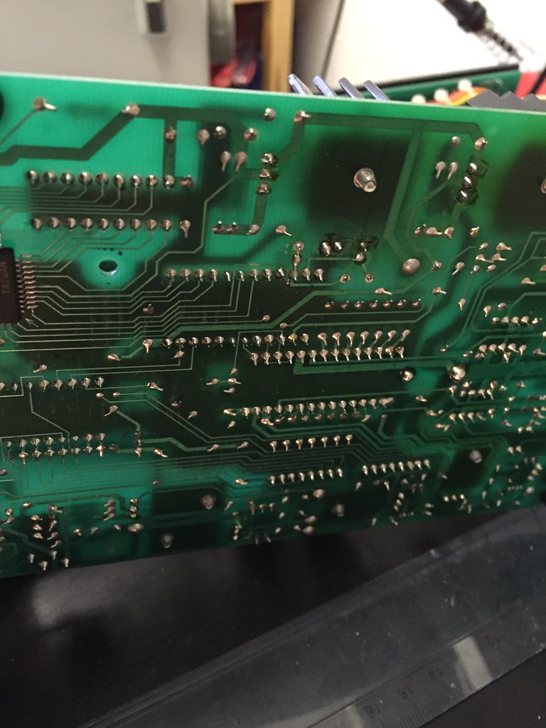
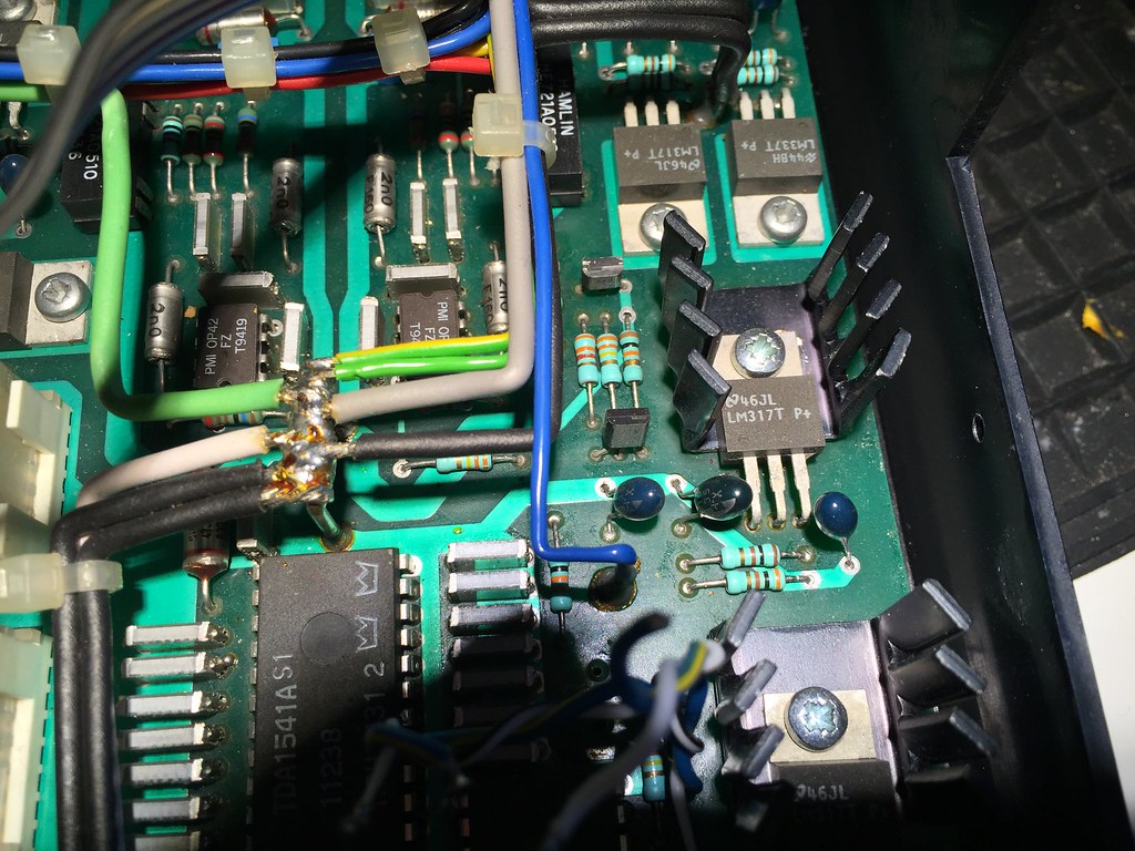
Main area I played with - I removed 2 caps and the original crystal, plus pulled a pin of the 7220 out of board and putl Flea's second feed at its output to the SAA7310

25149659875_9f827fe3be_b.jpg


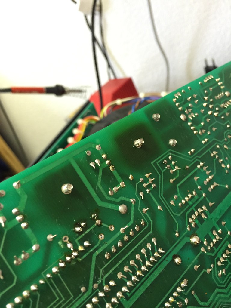
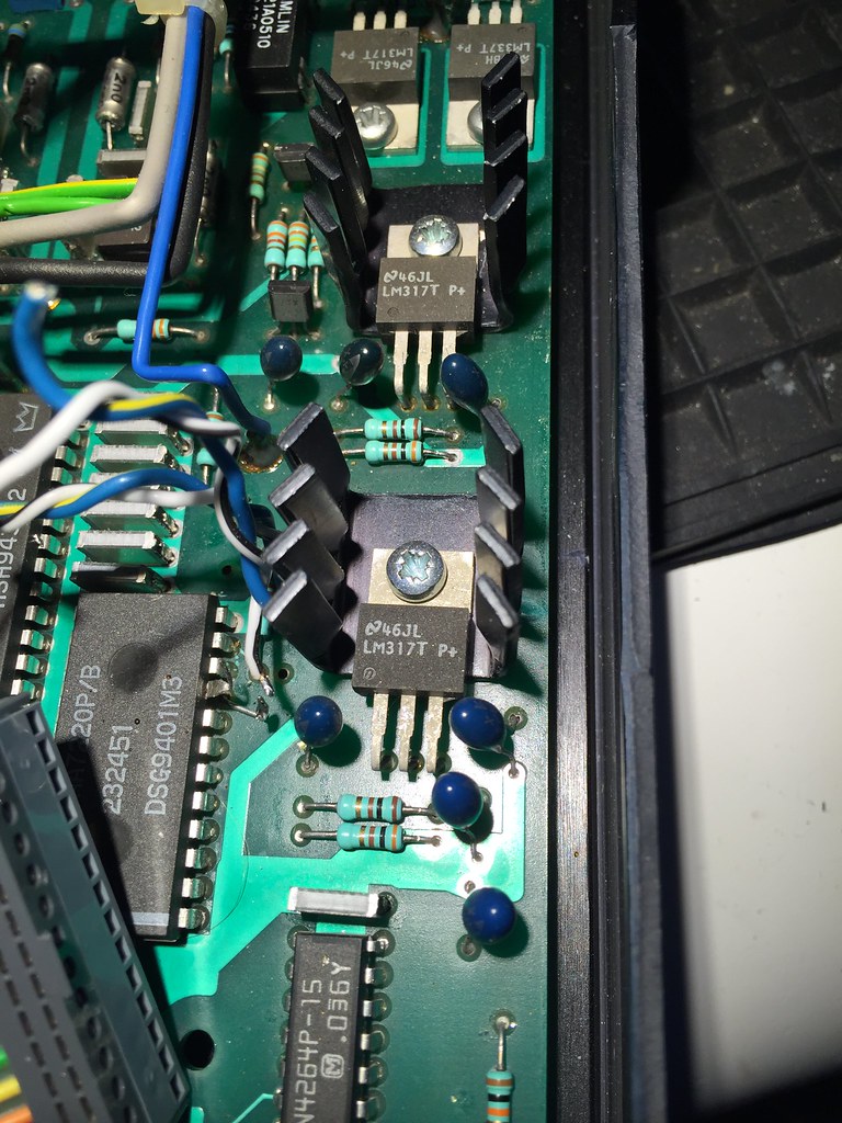
Some of the LM317 regulator joints looked cooked, and I was hopeful I had missed a failed one...but not, continuity still good - I just reflowed them all.
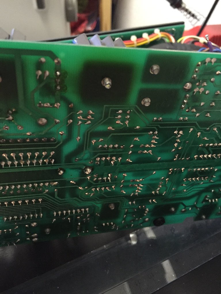
Bottom of main PCB;
24519027834_265487ee2f_b.jpg

25056419771_4b70a2e791_b.jpg

24781952199_4a2da7fd85_b.jpg


Richard
 
I bought a working Philips CD931 a few weeks back, uses a cdm9/65 mech. I soak tested it for a few days and it works fine. So I swapped the laser into the CDIs Pro mech last night.

The small torx screws holding laser to mech were *really* tight - I normally use an allen key of right size to undo them - no way with this one. Even with right sized driver I still needed great leverage to loosen them!

25148478284_bd759efee5_b.jpg


No change, fault exactly same - which is kind of good because I now have a spare laser, but a pain in the ass because I still need to find the fault.

I think I am going to remove the mods I've done, and re-install stock crystal as a first step - I really do not think it can be the cause, but best I rule it out I think.

Then I start swapping out the tants in small batches - none of them are reading short that I can measure, but at this stage it is either a cap or a chip - I was listening to the damn thing when it failed, it just stopped!

Richard
 
So, after far too much procrastination, and buying another CDP, I decided it was time to do some more work on CDI. I figured I may as well remove the Flea and dedicated xer/PSU as a first step, both to rule it out and because I want to mount this all better anyhow, preferably with one of Tony's MTPR boards hanging off 2nd xer winding for a dedicated 5v supply to 7220 (I have all bits in stock, just not progressed yet).

Working under bright light, I find a very discoloured tant on...the 5v rail feeding the 7220...the 317 reg was one of the ones I mentioned above as having dodgy looking cooked joints...why didn't I turn PCB over and look at the tants... Any bets on whether this is root cause?

25886164625_4fe196369e_b.jpg


25765380412_82285df70f_b.jpg


Still going to fit stock clock back in first, test, then replace all 3 of the tants on that reg.

Richard
 
I just measured all voltage lines again, everything checks out ok with a DVM - maybe I need to get a scope onto them and see if they are noisy?

Only slight irregularity is +/- 10v to servo board - one is sitting at 9.9v, other at -10.3v - not sure if this could be a problem?

The SAA7220 gets pretty warm - hot, but I can hold my finger on it no problem. The Flea when fitted was half covering this chip - could additional heat build up from this have caused a failure? Anyone had a 7220 failure, and what happened? I kind of assume it can't be related, as it's not reading discs and it's too far down the chain?

But then, the quickly flashing stop/start LEDs while spin motor pulses 3 times when it tries to read TOC also suggests a processor problem?

I wish there was a service manual available :)

Thanks, Richard
 
Only slight irregularity is +/- 10v to servo board - one is sitting at 9.9v, other at -10.3v - not sure if this could be a problem?
Not likely, well within 5% tolerance on voltage - which is not particularly critical here (motor is driven via PWM to target speed, controlled by servo)

The SAA7220 gets pretty warm - hot, but I can hold my finger on it no problem.... I kind of assume it can't be related, as it's not reading discs and it's too far down the chain?
Perfectly normal - the 7220 draws about 200-210mA at 5v = ~1W. Warm to hot. If it failed, it would not affect disc read at all.

But then, the quickly flashing stop/start LEDs while spin motor pulses 3 times when it tries to read TOC also suggests a processor problem?
No actually that's exactly what should happen on these players/ with saa7310 servo chipset - my CD2 does this and reads perfectly.

Wil have a think...


ETA: here's the servo SAA7310 datasheet in case you need it :) - Let me know if you need the SAA7210 datsheet instead, I have that too.
 
Thanks Martin - especially for confirmation on flashing LEDs - I've never noticed before...but then I guess my CDI has always had a disc in it. But good to know it is behaving normally, just not reading TOC.

I just looked at 7310 ds again - there are a couple of electrolytic caps on PLL and HFI data slicer pins. These are tiny reddish brown tants in the Naim I think - need to check values of them and see if I have something to replace them with.

I do this and check all supply lines for noise with a scope (or, try - I've forgotten more than I remember and couldn't do this well last time I tried - shit, when I was a kid in the workshop I only used a scope, DVM was for field service only!).

Richard
 
Another few unsuccessful hours - checked all the rails, all are clean. Then decided to go back to basics and ended up chasing my tail - I tried to measure laser RF - nothing. I look at the lens - it tries to focus up and down, but no red glow. Had I really missed something so obvious. End up tracing tracks from tda8808, laser and back to a transistor...hanging off the transistor emitter is the lid switch...which I'd left disconnected while measuring rails for noise...doh. Laser lights up when lid closed :) I was so pissed off, I just shorted out the switch (which I should have done before) and put it all back on the shelf for another day, LOL.

Richard


advertisement


Back
Top