advertisement


Flea and other mods to CDi...

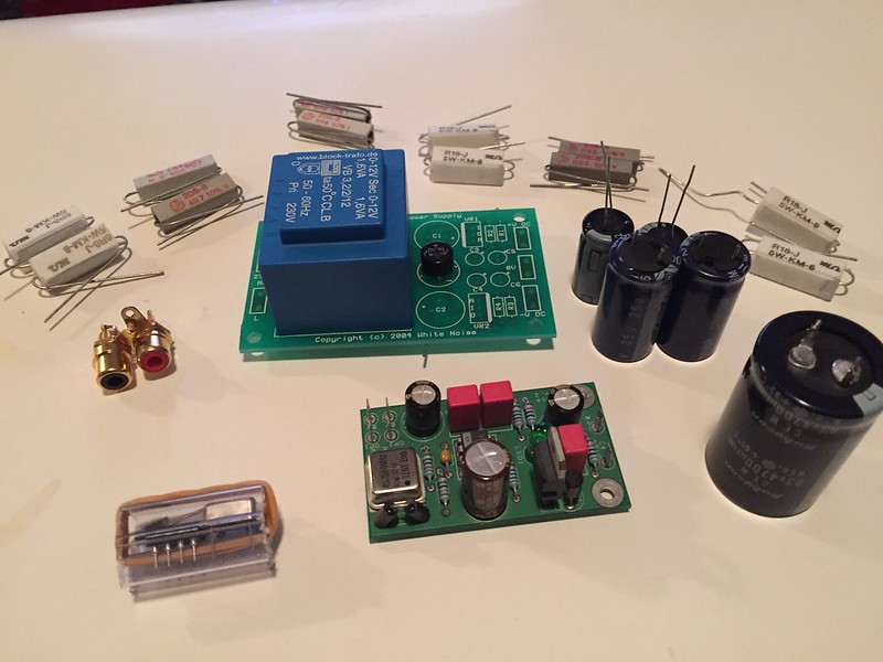
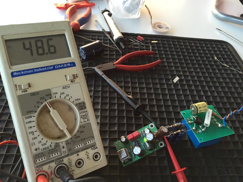
You can run the resulting 35vDC or so straight in if you ensure the first cap has a suitable rating. Burning a bit off using CRCRC after your rectifier would certainly do no harm (R of the order of 10ohms or more just fine) . the small 1.6VA transformer is all you need is since the flea will only draw 15-20mA (0.7Va at 35vDC) when running.
 
Yes it does Graham, good call.

... it's the 10K/3.3uF in the input cap multiplier. Take it down to 1k-2k2, and use a bigger cap instead (tant or reasonable electrolytic). Original value tends to 'starve' the 7812 voltage reg resulting in higher than expected DC output z to the opamp. One of the many things I have worked at since (its a project over 6yrs now :eek: )

Just reading up on this flea thread I missed.

I have been using 1K and a 47uF Nichicon Muse electrolytic in the fleas input filter and feed it with a 10-0-15 2VA transformer with a 680uF smoothing capacitor, no series R as the transformer secondary has more than enough secondary R

Tony
 
5.5 years after originally posting this thread, guess what I intend to do over Christmas this year :)

23616838710_78272a3947_c.jpg


I will just focus on fitting the Flea with a dedicated PSU - CRCRC filter (using 6.8 or 18 Ohm resistors for the R part - any idea what is better? I'm thinking a pair of each [on both positive and negative lines between caps]).

Not sure if I bodge the PSU PCB I have, or just dead-bug everything on top of the transformer - need to see how much space I have, and what sensible mounting options are. I won't have the Maplin snubbers beforehand (RG22y) - so need to leave space for them too.

One question - do I just remove the stock crystal, and solder in the Flea's o/p as close to the pads as possible, with as short a lead as possible?

Thanks, Richard
 
Yes. Remove the crystal and two tiny (33pf ish) loading capacitors adjacent, leaving the resistor between pins 10 and 11. Then feed your new clock in to pin 11 of the SAA7220. Tie the 0v side of your signal coax/ twisted pair as close as poss to the 0v plane here (e.g. to one of the 0v connections vacated by removing the loading caps)

Edit to add - bonus point while you have the thing apart. The SAA7220 sends the system clock (11.28Mhz) from pin 9 to the decoder upstream (which controls flow of data off disc, 'slices' it does the EFM and sends an I2S-format signal to the digital filter - the 7220). You'll find a low-value resistor adjacent which is connected directly to pin 9 of the '7220. Remove it, or lift the '7220' end of it, and feed this signal from the second output of the flea instead. NB you'll need a second SMD resistor of 47-10ohms on the flea pcb to use the second output.

PS suggest you see post 16 above and tweak the flea board values before you fit it.
 
Fantastic, thanks Martin - I just RTFM'ed the manual on Acoustica :) I'll order some SMD 100Rs now.

How far should I increase the value of the cap on the input multiplier if reducing the R value? And I assume keeping it a film is best?

Lastly - I bought this Flea ready built on here; it has the wrong oscillator currently. Guido provided a socket with the correct crystal for my CDI, but I am assuming I am better resoldering it directly to the board?

Thanks again, Richard
 
say 100uF of electrolytic will be just fine with the lower resistance. Very uncritical.

As for the rest - I solder mine butl even Tentlabs socket them so don't worry about it. The canned oscillator actually has the local decoupling cap inside it, so not the same problem at all as, say, socketing very fast opamps and wondering why they're not happy.
 
Great, thanks again - surprised I'm actually going to do this after 8 years or so :)
 
Built up the PSU today;
23319939414_c1a49b76c7_c.jpg


And modified the Flea - fitted correct Crystal (with socket) for my CDI, changed input multiplier from 10k Ohm & 3.3uF to 1.8k Ohm and 94uF (2x 47 uFs in parallel). Success;
23577863449_9424641f3f_c.jpg


But, voltage is very high at 48.6v - the Flea multiplier caps are only 50v (and the 2 smaller PSU smoothing caps only 35v...they didn't blow!). The transformer is supposed to be 12v dual secondary, but even with Flea connected it is measuring 39v AC across both secondaries! Input from mains is 231v, and it's a German 230v transformer. I can only assume transformer is out of spec?

Will the load increase when I connect the crystal output to my CDI and drop input voltage? I don't think so. Otherwise I need to order some higher voltage caps - nothing on the Flea is getting hot - I think the BC547 is OK, but all the caps are only 50v parts.

Either that or I only run one secondary on the transformer? Should give me around 27v raw supply. Which is better? My experience says that multipliers like to be given some work to do...

Thanks, Richard
 
I also tried adding another larger smoothing cap and 2 more 10 ohm resistors to make a CRCRC;

23866107511_362d16e09a_c.jpg


No difference to voltage - assuming I have enough room in CDI then three smoothing caps has to be better than 2... :) But, am I better off mounting the larger smoother close to raw supply, and the other 2 close to the Flea, or can they all go close to the raw PSU? Distances involved are no more than 10-15cm of wire I guess.

Thanks, Richard
 
Oh, and note my first DIY snubber :) I bought loads of film caps and higher wattage resistors recently, Maplin want £2.40 for one of their RG22Ys and do not ship to Swissieland...so it seemed rude not to :)

Richard
 
Just time for one quick observation as dinner is close.
Small transformers have huge regulation, that is on load voltage compared to off load voltage. Put a dummy load on and the voltage will drop.
Also on no load the series resistors are dropping 0v. V=IR and I is 0 on no load.
 
Thanks - but that is with the Flea connected - will connecting the Flea to the 7220 input really increase load so much? Think I am going to try anyhow, but for me the Flea should be a higher load than actually connecting it to the CD player? Or am I simply wrong (kind of hope so ;)).

Thanks, Richard
 
In my head simple sums go something like 3K on the input to the flea will draw around 10mA at 30V and dissipate 0.3W so you could use 2 x 6K 1/4W in parallel unless you have 1/2W resistors. They will get hot so dont touch!

Then see how the voltage settles.

Flea will draw around 6 or 7 mA from memory, clock when in circuit around 5 or 10mA
 
Thanks - the regulator on the Flea is outputting 13.7v, guess I should check crystal has 5v at its input (1.9v at output using DVM).

Richard
 
13.7v after the 7812 is fine.

Are you using that bridge rectifier across both secondaries connected in series? It would explain your raw DC voltage as 24v x 1.41 x say 115% (for low regulation) - 40odd volts about right! Not good.

Can you either just wire the bridge across one secondary (or both secondaries in parallel), or find two diodes (1n4007, anything in fact) and rewire your supply as a fullwave rect using two diodes and the centretap insteaad? Either should then give about 20-22vdc output which is fine.

The flea is a feedback reg so will correctly show 5v +/- a tad at the XO socket without the XO plugged in, for testing first.

Total flea current draw: the opamp draws about 8mA, the XO 3-5mA, add 2-3mA through the 7812 reference leg to led = about 15-20mA all-in. This does not change when driving a clock signal into the player (very high impedance input when the 7220 is powered, but adds 2-3mA draw if the clock is on and the 7220 unpowered i.e. player off, clock live while testing)


[ Post supper here, brandy opened - apols if this is garbled ;) ]
 
Thanks Martin & Tony - I have spare diodes, and I know from experience how full wave improves sound quality...especially powering a crystal :) I rewire tomorrow...once the zwechgenschnapps has lost is ability to slur my brain.

With full wave though, the snubber still goes across full AC output?


Happy Christmas All!
 
No, two snubbers, one across each secondary (i.e. joined at centre tap) - because each winding half is excited separately.


Happy Christmas indeed :)
 
Reconfigured it this morning - I only had IN4001 diodes in my spares box, but voltage/current is low enough for this to suffice I think.

Testing it without the load connected (I never did this with the original - I tested it with caps connected, but not the Flea), why am I getting a lower DC voltage than with load connected?

No load;
23354779953_8d8af53957_c.jpg


Smoothers and Flea connected;
23685901490_d4075f4216_c.jpg


If I was really bothered I have a scope now, and would expect to see a mess of AC at the ouput with no load if I measured, that then cleans up with a load applied?

Last question for now - how critical are the values for the snubbers? I'm now using .082 uF mustards (probably a criminal waste, but there you go :)) - is that sufficient? All a bit moot for this PSU I guess, where it probably makes not a lot of difference - but I want to apply the same to other pre-amp PSU circuits in due course, so would like to understand how to select best values (I will post in the snubber thread when I get time too).

Right - off to rip open my cherished CDI...do I fit snubbers on it's 2 bridge rectifiers too at same time?!

Thanks, Richard


advertisement


Back
Top