
You are using an out of date browser. It may not display this or other websites correctly.
You should upgrade or use an alternative browser.
You should upgrade or use an alternative browser.
Flea and other mods to CDi...
- Thread starter Dowser
- Start date
Dowser
Learning to bodge again..
So, to try and clarify & summarise my situation. I now have 2 Naim CDIs;
CDI #1 - original subject of this thread. I picked this up faulty many, many years ago and replaced the laser and disc platter after previous Italian owner bodged a repair. I loved it, and after much procrastination, fitted a Flea into it over Christmas 2015. It stopped reading discs suddenly half way through a CD a few months later, and has resisted repeated attempts by me to fix it. Disc pulses 2 or 3 times when it tries to read TOC, fails.
CDI #2 - I bought this off Laverda a few weeks back, with the intention of using it to fix CDI #1. I bought it with distorted audio output, but it read and played discs...until I got my fingers into it and broke it by manually stopping the spinning disc - it now slowly spins the disc backwards regardless of lid switch, does attempt to read TOC but fails due to backwards motion of disc.
As per a few posts above, CDI #2 suddenly started working for a while a few nights back - played OK for about 5 hours but then failed again on overnight soak test.
I tried changing the NE5532 opamp on the main board (where the reverse drive signal originates) of CDI #2, but as expected it's not that.
While comparing CDI #2 static voltages with CDI #1, I decided to also check the CDI #1 lid switch issue I detected earlier (one switch connector pin has 2.5v on it when it should not) - oops, a self induced short from when I resoldered all connector pins!
Given previous comparisons I did when I first got CDI #2, I know CDI #1 has problems with both laser unit and servo board. Now it looks like servo board was my screw-up, I am also wondering same about the laser. I transplanted a CDM9/63 laser unit into it (rather than the more normal CDM9/44 donor) - CDM9/63 was working in it's original Philips host, but I never refitted the original laser from CDI #1 into it the Philips host to confirm it still worked.
Anyhow, next step for me will be to swap the laser units between the 2 CDIs and compare again.
Slow but steady progress")
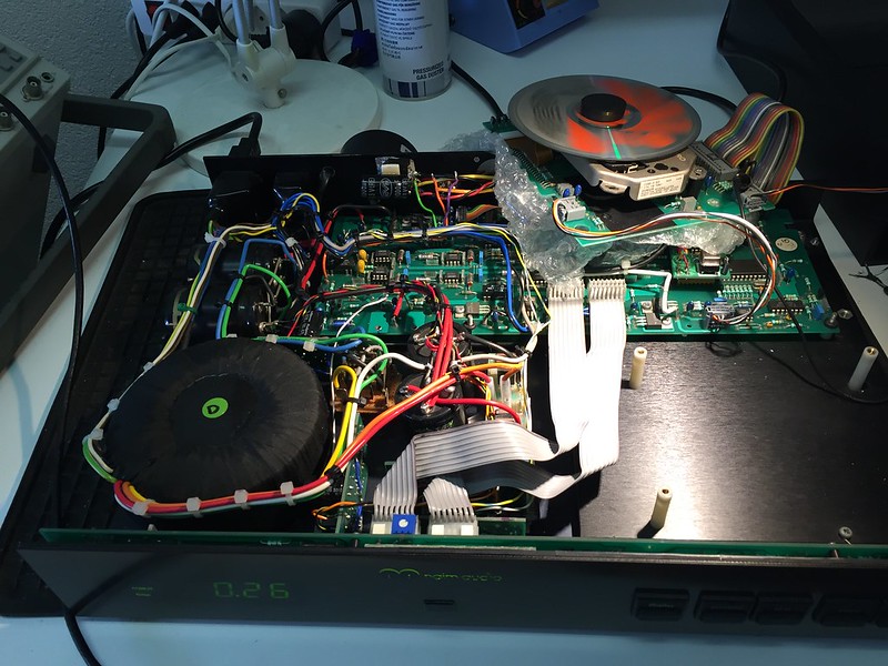
Photos;
Temporarily functioning CDI #2
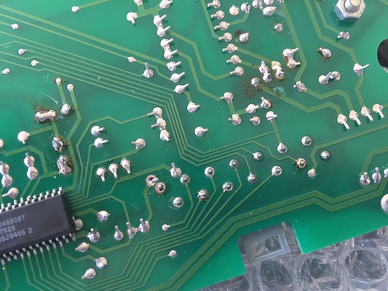
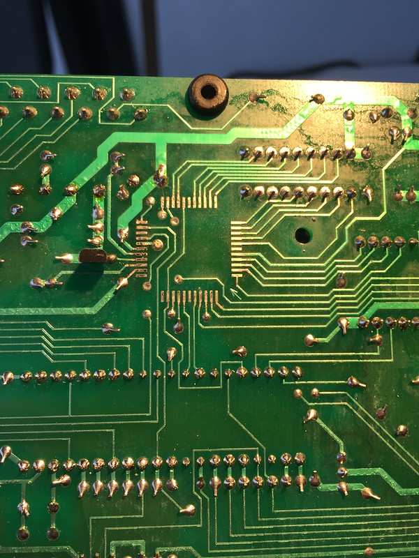
Self-Induced Short Circuit on Servo Board of CDI #1
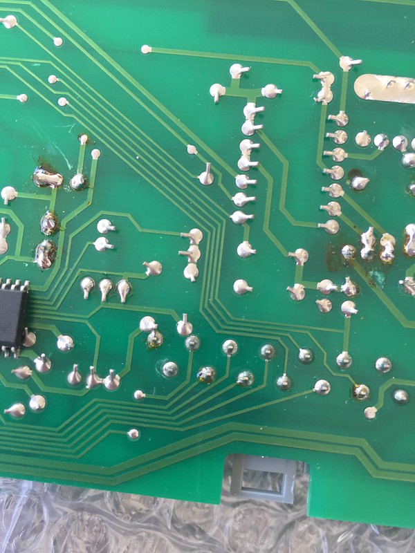
The tracks are *very* close together...in my defense
Richard
CDI #1 - original subject of this thread. I picked this up faulty many, many years ago and replaced the laser and disc platter after previous Italian owner bodged a repair. I loved it, and after much procrastination, fitted a Flea into it over Christmas 2015. It stopped reading discs suddenly half way through a CD a few months later, and has resisted repeated attempts by me to fix it. Disc pulses 2 or 3 times when it tries to read TOC, fails.
CDI #2 - I bought this off Laverda a few weeks back, with the intention of using it to fix CDI #1. I bought it with distorted audio output, but it read and played discs...until I got my fingers into it and broke it by manually stopping the spinning disc - it now slowly spins the disc backwards regardless of lid switch, does attempt to read TOC but fails due to backwards motion of disc.
As per a few posts above, CDI #2 suddenly started working for a while a few nights back - played OK for about 5 hours but then failed again on overnight soak test.
I tried changing the NE5532 opamp on the main board (where the reverse drive signal originates) of CDI #2, but as expected it's not that.
While comparing CDI #2 static voltages with CDI #1, I decided to also check the CDI #1 lid switch issue I detected earlier (one switch connector pin has 2.5v on it when it should not) - oops, a self induced short from when I resoldered all connector pins!
Given previous comparisons I did when I first got CDI #2, I know CDI #1 has problems with both laser unit and servo board. Now it looks like servo board was my screw-up, I am also wondering same about the laser. I transplanted a CDM9/63 laser unit into it (rather than the more normal CDM9/44 donor) - CDM9/63 was working in it's original Philips host, but I never refitted the original laser from CDI #1 into it the Philips host to confirm it still worked.
Anyhow, next step for me will be to swap the laser units between the 2 CDIs and compare again.
Slow but steady progress
Photos;
Temporarily functioning CDI #2
Self-Induced Short Circuit on Servo Board of CDI #1
The tracks are *very* close together...in my defense
Richard
Dowser
Learning to bodge again..
A bit more work done;
CDI #1 - swapped the donor 9/63 laser with the original from CDI #2 (after testing again that it works fine in the Kodak photo player), and it is now spinning up and attempting to read the TOC. It fails ...but both servo/laser combos now perform exactly the same in both machines so I assume are good now.
The 9/63 does not work in the Kodak donor - so is either faulty (although I tested it in it's Philips CD donor as OK before swapping a year or so ago), or the 9/63 laser is different from the 9/44 - they look exactly the same though. Job for another day is to refit 9/63 into Philips to confirm.
I then took full measurements of #1 servo board and all regulated supplies & opamp on main board that drives the disc motor, ready for a comparison with #2. Results;
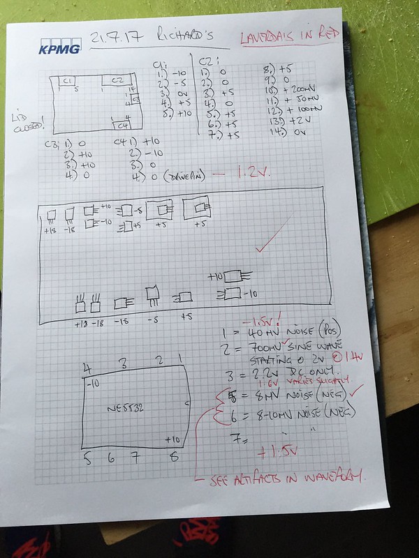
Output of first stage of NE5332 on pin 1 is at -1.5v - with pins 2 & 3 both at .6v lower on the machine with disc spinning backwards. On second stage input pins 5 & 6 waveforms and DC potential look OK, except for the weird signal shown below.
I am at a loss to explain it - any ideas anyone?

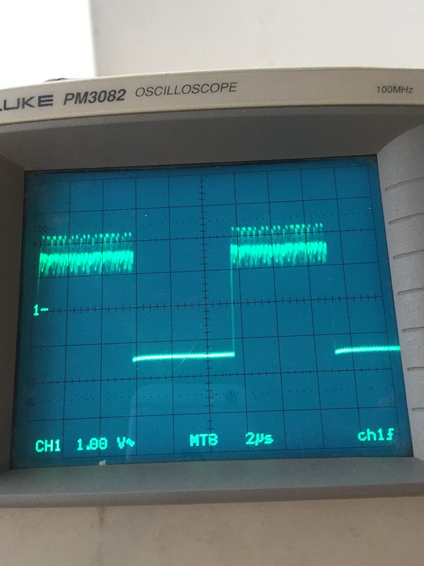
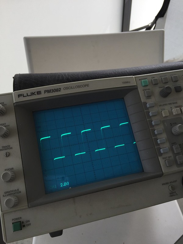
I also soldered litz wire to the MCS signal coming out of the saa7310 - this is how it looks on the scope in standby (with disc spinning backwards), with a service manual view of what should be seen in standby (MC-Signal waveform);
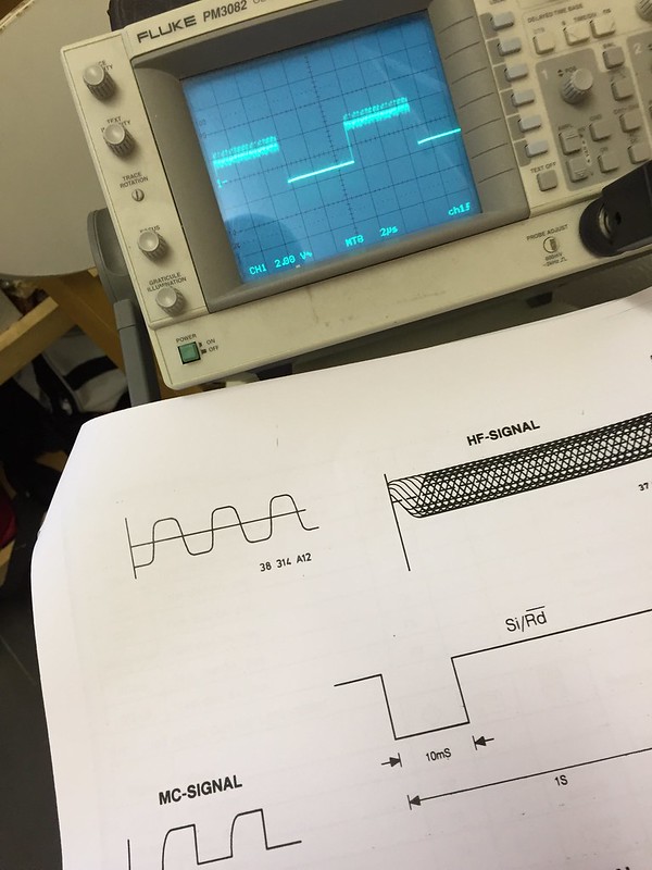
Is that noise at the top of the waveform causing my issue? I need to compare with #1 I think.
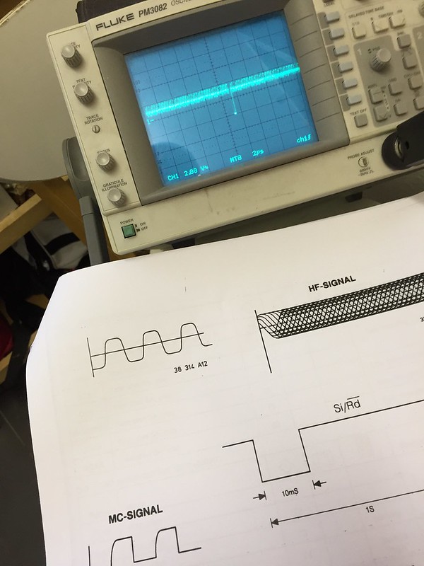
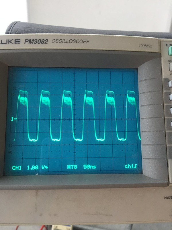
The waveform does the right thing while trying to read TOC (98% duty for .2 of a second) - but still has that noise on top;
I even checked the SWAB signal from the processor to 7310 to ensure it is giving the correct motor start signal - I am learning far more about CD players than I ever intended to
Next step for me is to compare the MSC signal out of the saa7310 on CDI #1 to see if it has the same noise on top as CDI #2 does.
It is also interesting to note that once play is initiated, ultimate speed control is performed based on filling of the DRAM's FIFO buffer - this is the separate chip that is running as hot as the saa7220 on CDI #1, and is just warm on CDI #2 - still no idea which is correct - the DRAM chip also has it's own 5v supply in the Naim, with a heatsink same as the 7220's. Anyone ever measured operating temp of the MN4264 DRAM chip?
Onwards and upwards
Richard
CDI #1 - swapped the donor 9/63 laser with the original from CDI #2 (after testing again that it works fine in the Kodak photo player), and it is now spinning up and attempting to read the TOC. It fails
...but both servo/laser combos now perform exactly the same in both machines so I assume are good now.The 9/63 does not work in the Kodak donor - so is either faulty (although I tested it in it's Philips CD donor as OK before swapping a year or so ago), or the 9/63 laser is different from the 9/44 - they look exactly the same though. Job for another day is to refit 9/63 into Philips to confirm.
I then took full measurements of #1 servo board and all regulated supplies & opamp on main board that drives the disc motor, ready for a comparison with #2. Results;
Output of first stage of NE5332 on pin 1 is at -1.5v - with pins 2 & 3 both at .6v lower on the machine with disc spinning backwards. On second stage input pins 5 & 6 waveforms and DC potential look OK, except for the weird signal shown below.
I am at a loss to explain it - any ideas anyone?
I also soldered litz wire to the MCS signal coming out of the saa7310 - this is how it looks on the scope in standby (with disc spinning backwards), with a service manual view of what should be seen in standby (MC-Signal waveform);
Is that noise at the top of the waveform causing my issue? I need to compare with #1 I think.
The waveform does the right thing while trying to read TOC (98% duty for .2 of a second) - but still has that noise on top;
I even checked the SWAB signal from the processor to 7310 to ensure it is giving the correct motor start signal - I am learning far more about CD players than I ever intended to
Next step for me is to compare the MSC signal out of the saa7310 on CDI #1 to see if it has the same noise on top as CDI #2 does.
It is also interesting to note that once play is initiated, ultimate speed control is performed based on filling of the DRAM's FIFO buffer - this is the separate chip that is running as hot as the saa7220 on CDI #1, and is just warm on CDI #2 - still no idea which is correct - the DRAM chip also has it's own 5v supply in the Naim, with a heatsink same as the 7220's. Anyone ever measured operating temp of the MN4264 DRAM chip?
Onwards and upwards
Richard
Dowser
Learning to bodge again..
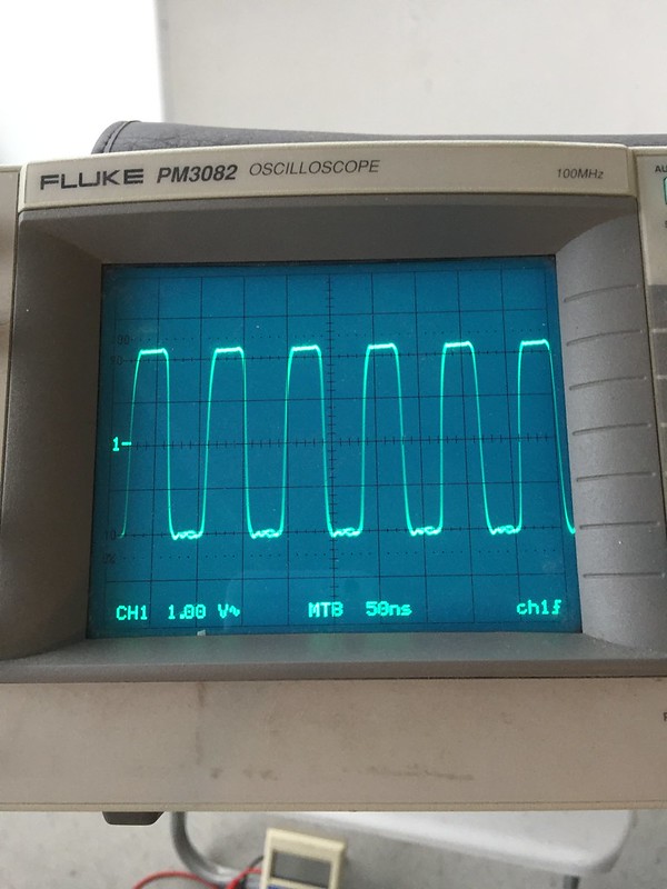
Hmm - OK, that noise on the MCS signal is the problem - these are the same waveforms from #1;
At standby
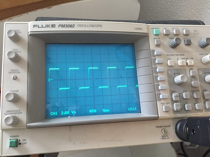
Reading TOC
Now to find out where it comes from (any ideas?!) - between output of saa7310 and motor drive opamp it passes through one of the Motorola processor pins, through a 39k resistor, a small 22n film cap and then I need to draw out the full opamp circuit.
Going to measure all processor pins of #1 now, to compare to #2 later.
Thanks, Richard
At standby
Reading TOC
Now to find out where it comes from (any ideas?!) - between output of saa7310 and motor drive opamp it passes through one of the Motorola processor pins, through a 39k resistor, a small 22n film cap and then I need to draw out the full opamp circuit.
Going to measure all processor pins of #1 now, to compare to #2 later.
Thanks, Richard
Dowser
Learning to bodge again..
Haha - I'm desparately avoiding going down that route, it has never proved that successful unless I can prove the fault first.
However, I isolated the connection from saa7310 MCS out put and the motor drive opamp - it's definitely either coming from saa or the processor chip - I will try lifting the MCS pin off the PCB next and try again.
However, I isolated the connection from saa7310 MCS out put and the motor drive opamp - it's definitely either coming from saa or the processor chip - I will try lifting the MCS pin off the PCB next and try again.
Dowser
Learning to bodge again..
Have you checked power rails for noise?
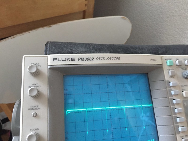
Yes, and all clean. However, I did pick up a similar trace to this on one of the processor earth pins just before I stopped last night - no idea if magnitude is same, need to check when I get back into it. How can this sort of noise be on an earth track? My probe negative is connected to the main star point in middle of PCB;
Thanks, Richard
Dowser
Learning to bodge again..
So, if I lift the pin of the saa7310, there is noise at the output - the motor drive signal is gone, just a hash of noise. The rest of the circuit down to the drive opamp is quiet.
I assume the saa7310 - off to see if I can order a new one, or have to transplant one from a donor. I will also need to order a proper magnifier lamp - my eyesight is no longer good enough for this shit! Any recommendations for a good one?
To note though - I am still getting the above noise signal on the star point earth, with earth and signal pin connected at same point. Can I ignore this, or is it significant? It can't be good to have an return line polluted in such a way? What could cause it?
Thanks, Richard
Dowser
Learning to bodge again..
Bit more work on CDI #1 tonight - I swapped the overheating DRAM chip. It now runs cool, but still fails to read TOC.
What it does do now, but did not before I think, is that the platter motor drive (MSC) signal quickly drops from default 98.2% to around 90% and varies. I can only assume this means that the DRAM is being filled, and 7310 is adjusting drive signal appropriately.
Eye pattern also looks good and is 1.2v P-P while trying to read TOC (1.2v is OK, yes?).
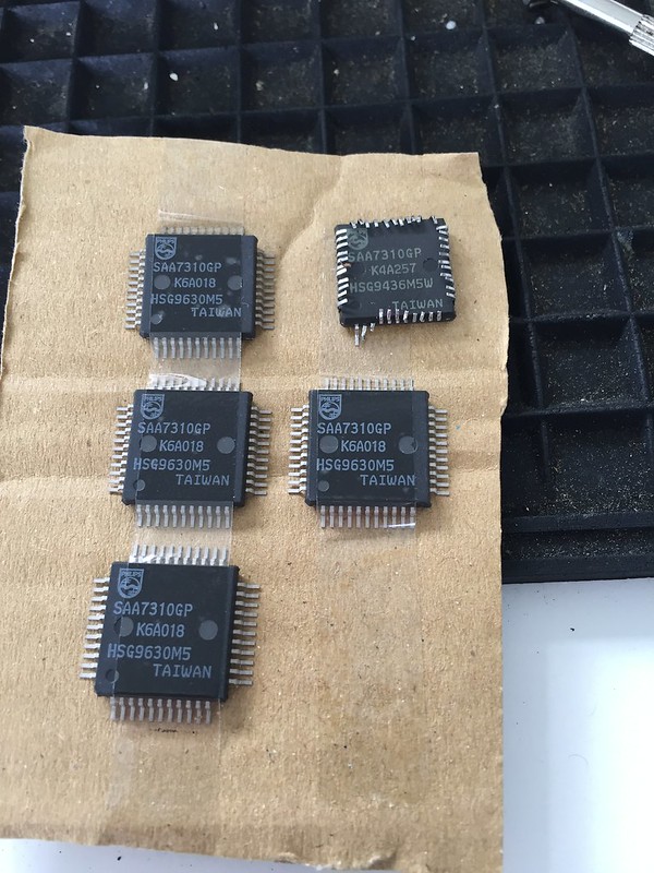
I ordered 4x saa7310gp chips yesterday, plus 2 magnifier lamps (one fixed, one to wear on head...hopefully one will give me the necessary eyesight to remove a damned 44 pin SMT without damage!).
Next stage for both players currently is to replace the 7310 I think, but am also ordering the low value tants used around the 7310 and associated chips too just in case.
I have to be able to get these damned things working again...
Richard
What it does do now, but did not before I think, is that the platter motor drive (MSC) signal quickly drops from default 98.2% to around 90% and varies. I can only assume this means that the DRAM is being filled, and 7310 is adjusting drive signal appropriately.
Eye pattern also looks good and is 1.2v P-P while trying to read TOC (1.2v is OK, yes?).
I ordered 4x saa7310gp chips yesterday, plus 2 magnifier lamps (one fixed, one to wear on head...hopefully one will give me the necessary eyesight to remove a damned 44 pin SMT without damage!).
Next stage for both players currently is to replace the 7310 I think, but am also ordering the low value tants used around the 7310 and associated chips too just in case.
I have to be able to get these damned things working again...
Richard
Dowser
Learning to bodge again..
Help!
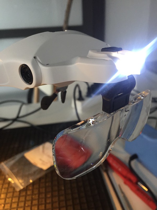
I have received the replacement saa7310s, replacement low value decoupling tants (2.2 and 4.7uf) and the head based magnify glasses.
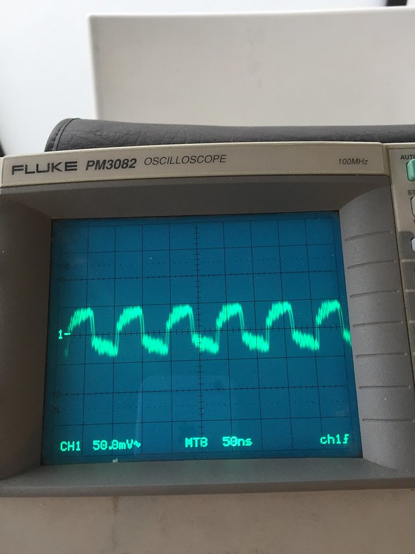
Before stepping off the ledge that is replacing the 44 pin SMD 7310, I decided to swap all decoupling tants first. No change. I still have the following standby state artifact on the MSC (platter motor control) signal from the 7310, causing the platter to spin backwards;
It should look like this;
I then go back and measure the main clock output from pin 9 of the SAA7220 to the SAA7310 - arrgh! Why didn't i spot this before? I see a similar artifact on top of the waveform;
So I then split pin 9 of saa7220 from the saa7310 input pin, and get this at 7220 output which looks fine;
On the saa7310 input pin I see;
What to say? Against my better judgement I am going to attempt replacing the saa7310 tomorrow - it *must* be either that or the processor injecting this noise at this stage. Please save me if you have a better idea!
I have these to help, but it will still be a horrible job
Cheers, Richard
I have received the replacement saa7310s, replacement low value decoupling tants (2.2 and 4.7uf) and the head based magnify glasses.
Before stepping off the ledge that is replacing the 44 pin SMD 7310, I decided to swap all decoupling tants first. No change. I still have the following standby state artifact on the MSC (platter motor control) signal from the 7310, causing the platter to spin backwards;
It should look like this;
I then go back and measure the main clock output from pin 9 of the SAA7220 to the SAA7310 - arrgh! Why didn't i spot this before? I see a similar artifact on top of the waveform;
So I then split pin 9 of saa7220 from the saa7310 input pin, and get this at 7220 output which looks fine;
On the saa7310 input pin I see;
What to say? Against my better judgement I am going to attempt replacing the saa7310 tomorrow - it *must* be either that or the processor injecting this noise at this stage. Please save me if you have a better idea!
I have these to help, but it will still be a horrible job
Cheers, Richard
Dowser
Learning to bodge again..
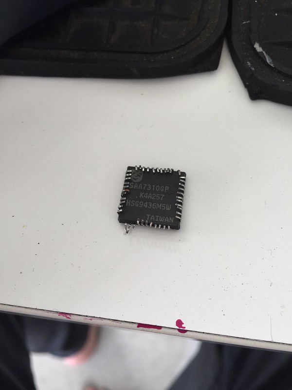
Took the plunge today after first checking every pin of the saa7310 with a scope first - interestingly there are 4 test pins on the chip - 3 of them have a square wave on them, and 2 of the 3 have that noise at the top. Unfortunately the datasheet doesn't show any detail on what the test pins relate to, would love to know.
I need a break before mounting the new one...
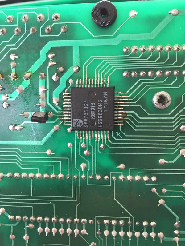
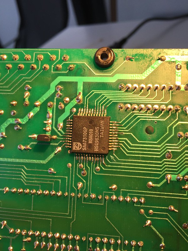
Old one out;
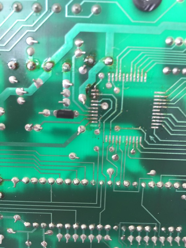
PCB before cleaning up;
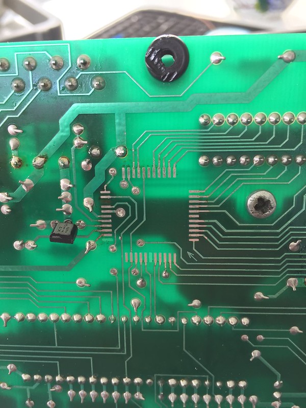
After cleaning and ready for new - only tracks lifted were those not connected to anything;
I need a break before mounting the new one...
Old one out;
PCB before cleaning up;
After cleaning and ready for new - only tracks lifted were those not connected to anything;
Dowser
Learning to bodge again..
Replacements from UTSource at $5 each;
In place;
That looks a better standby MSC signal
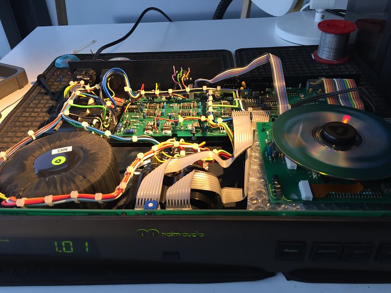
Mech refitted, and playing a disc;
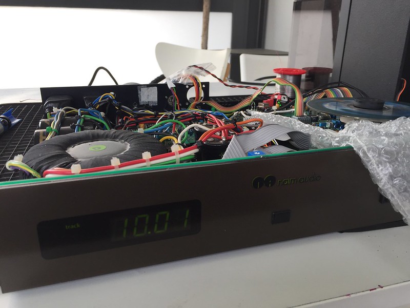
F*cking Yay - CDI #2 now reading TOC and playing So why did me stopping the disc platter manually by hand cause the 7310 to fail? I assume it was faulty already, as it seemed very weak at spinning the disc up compared to CDI #1. Now that it is fixed, who cares
I already replaced the 7220 which Laverda thought was causing the noisy audio out - I haven't listened yet, but audio signal looks clean.
Richard
In place;
That looks a better standby MSC signal
Mech refitted, and playing a disc;
F*cking Yay - CDI #2 now reading TOC and playing
So why did me stopping the disc platter manually by hand cause the 7310 to fail? I assume it was faulty already, as it seemed very weak at spinning the disc up compared to CDI #1. Now that it is fixed, who cares I already replaced the 7220 which Laverda thought was causing the noisy audio out - I haven't listened yet, but audio signal looks clean.
Richard
Dowser
Learning to bodge again..
It sounds very nice I am rather happy, to say the least!
Now to tackle my original CDI #1 that while sounding healthy while trying to read TOC, it doesn't. I had some advice from someone on DIY Audio I contacted to try scoping all supplies while it is trying to read TOC, to see if anything is breaking down - that will be my first task, along with replacing all the 7310 decoupling caps again.
If that don't work, and given the DRAM chip was seriously overheating, I will also replace the 7310 on that too
Richard
I am rather happy, to say the least!Now to tackle my original CDI #1 that while sounding healthy while trying to read TOC, it doesn't. I had some advice from someone on DIY Audio I contacted to try scoping all supplies while it is trying to read TOC, to see if anything is breaking down - that will be my first task, along with replacing all the 7310 decoupling caps again.
If that don't work, and given the DRAM chip was seriously overheating, I will also replace the 7310 on that too
Richard
martin clark
pinko bodger
Fantastic fix - well done with taking that on, and winning.
And very helpful documentation/pics for reference of others - thanks for documenting it.
Enjoy the sounds
And very helpful documentation/pics for reference of others - thanks for documenting it.
Enjoy the sounds
Dowser
Learning to bodge again..
Thanks All!
And I'm on a roll - I changed decoupling caps around 7310 and processor of CDI #1 (2x 2.2uf & 10uf for 5v of 7310, 4.7uf and 10uF for 5v of processor), no change, still unable to read TOC. MSC is spot on, and since changing DRAM chip I can see it filling up and the MSC fluctuating to control disc speed - eye pattern looks good and is at 1.2v.
So, I changed it's 7310 too - result - I now have 2 working CDIs
Much easier 2nd time around - its been nearly 30 years since I changed an SMD chip, this time no lifted tracks;
New one mounted;
And playing music
I am ecstatic So failure of my original flea'ed CDI was either DRAM or 7310 failing and taking out the other chip.
I now put them both back together and compare them - CDI #1 is currently stock except for new smoothing caps (I removed it's Flea early on in fault-finding), and Laverda's has 4 pole smoothing caps, a Flea and OPA627 audio opamps each fed it's +/- rails by ALWSRs (replacing original 317/337 regs). Only downside is Laverda swapped the double crown TDA for an R version - anyone got a Taiwan made late 1541 they'd sell me?
I then need to decide what to sell - I now have 4 decent TDA1541A based CDPs;
2x CDI
Woodside CD3
Cambridge Audio CD3
I will almost certainly sell one of the CDIs I guess, although for sure there is a certain benefit of having 2 of such a player...especially when they develop a fault...I would never have fixed mine unless I had bought Laverda's to compare I think.
Happy Days! Thanks for all the support.
Richard
And I'm on a roll - I changed decoupling caps around 7310 and processor of CDI #1 (2x 2.2uf & 10uf for 5v of 7310, 4.7uf and 10uF for 5v of processor), no change, still unable to read TOC. MSC is spot on, and since changing DRAM chip I can see it filling up and the MSC fluctuating to control disc speed - eye pattern looks good and is at 1.2v.
So, I changed it's 7310 too - result - I now have 2 working CDIs
Much easier 2nd time around - its been nearly 30 years since I changed an SMD chip, this time no lifted tracks;
New one mounted;
And playing music
I am ecstatic
So failure of my original flea'ed CDI was either DRAM or 7310 failing and taking out the other chip.I now put them both back together and compare them - CDI #1 is currently stock except for new smoothing caps (I removed it's Flea early on in fault-finding), and Laverda's has 4 pole smoothing caps, a Flea and OPA627 audio opamps each fed it's +/- rails by ALWSRs (replacing original 317/337 regs). Only downside is Laverda swapped the double crown TDA for an R version - anyone got a Taiwan made late 1541 they'd sell me?
I then need to decide what to sell - I now have 4 decent TDA1541A based CDPs;
2x CDI
Woodside CD3
Cambridge Audio CD3
I will almost certainly sell one of the CDIs I guess, although for sure there is a certain benefit of having 2 of such a player...especially when they develop a fault...I would never have fixed mine unless I had bought Laverda's to compare I think.
Happy Days! Thanks for all the support.
Richard