
chiily
PFM Special Builder
I've tested both amps now and they behave the same...which is great ") no, I mean it, consistently is the name of the game.
no, I mean it, consistently is the name of the game.
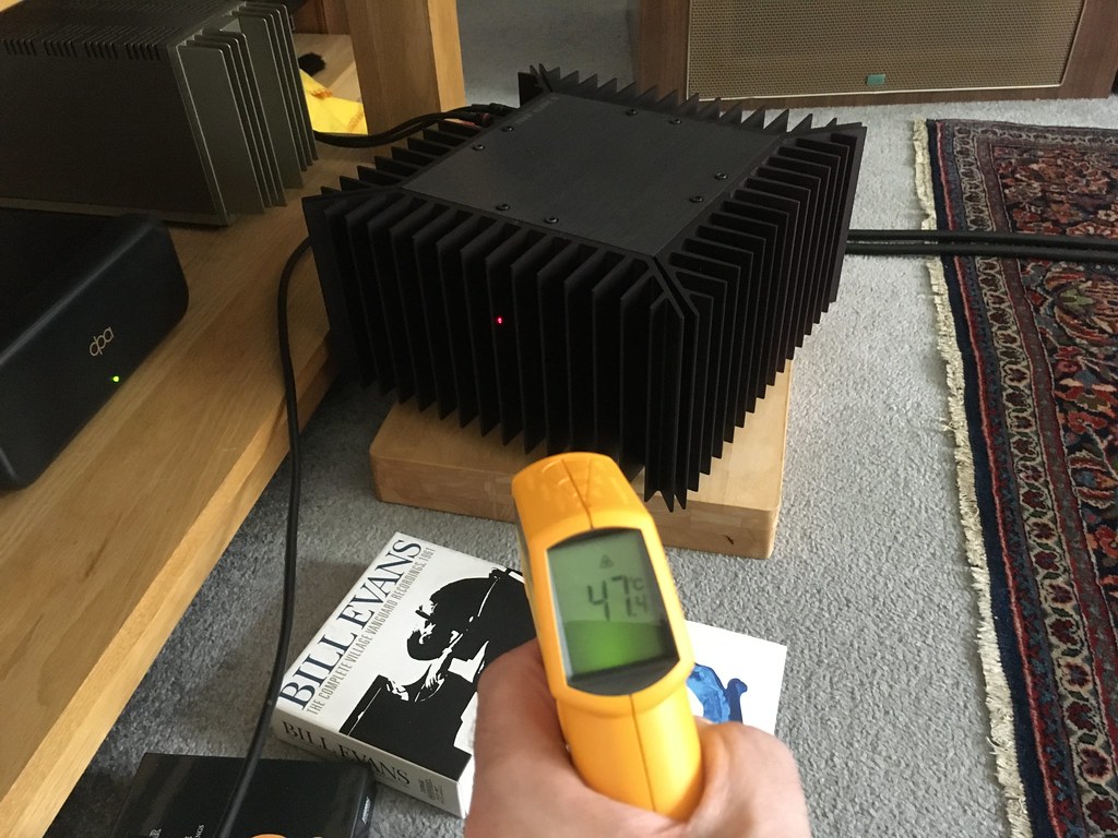
I have swapped the EF86s and the GZ32 between amps and still the same behaviour. Bulb lights, bright, voltage over the PSU starts to climb to about 240VDC over 10secs, then begins to fall back.
So, I think it is the bulb...I think like this...
With just the GZ32 installed and I get a good voltage out of the PSU. I add the other valves and the voltage begins to come up, valves begin to warm, pull more current, bulb restricts too much, and the voltage collapses. The bulb stays bright all the time.
If there was a short I wouldn't get up to 240VDC out of the PSU.
I have a halogen, 60W equivalent in the tester. Says it is 42W. I guess I should go for a 60W real, coal fueled bulb.
Does my thinking feel right?
no, I mean it, consistently is the name of the game.I have swapped the EF86s and the GZ32 between amps and still the same behaviour. Bulb lights, bright, voltage over the PSU starts to climb to about 240VDC over 10secs, then begins to fall back.
So, I think it is the bulb...I think like this...
With just the GZ32 installed and I get a good voltage out of the PSU. I add the other valves and the voltage begins to come up, valves begin to warm, pull more current, bulb restricts too much, and the voltage collapses. The bulb stays bright all the time.
If there was a short I wouldn't get up to 240VDC out of the PSU.
I have a halogen, 60W equivalent in the tester. Says it is 42W. I guess I should go for a 60W real, coal fueled bulb.
Does my thinking feel right?
 PXL_20211217_192929708
 2021-12-18_11-36-18
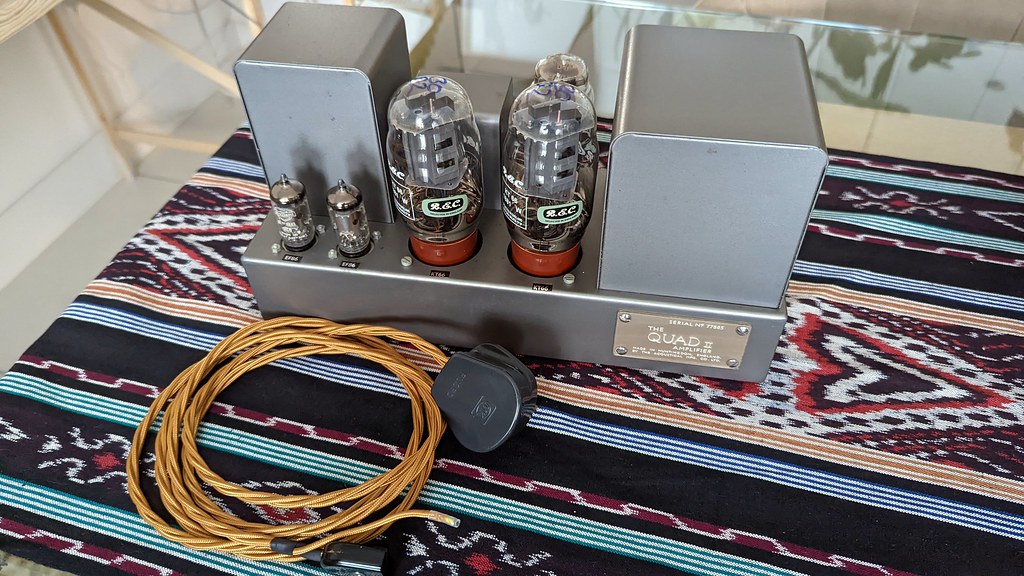 2021-12-18_10-10-34
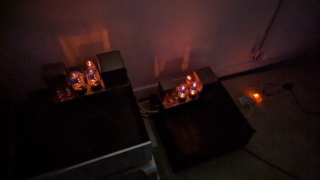 PXL_20211219_185356911
 PXL_20211219_185336774
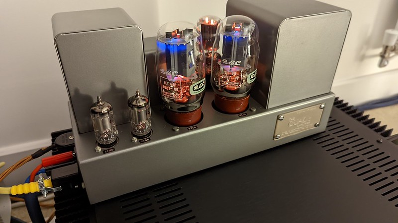 PXL_20211219_175500079
 PXL_20211219_175520424
 20211220_Voltages