
Arkless Electronics
Trade: Amp design and repairs.
For those not wishing to DIY it I offer a full repair and rebuild service for all major brands of vintage valve and SS amplifiers.
If I remember correctly the 6 pin jones used on Quads has one end pair of pins further away from the centre than the other so they cannot be inserted wrongly.
Try not to get it the wrong way round or you will put 6.3 volts AC into the output of your preamp.....
")
 PXL_20211215_202410303 by Garf Arf, on Flickr
 PXL_20211215_195300156 by Garf Arf, on Flickr
 PXL_20211215_203325227 by Garf Arf, on Flickr
One question is whether valve amps can be run without a load connected to the speaker terminals? I seen various answers on various forums.
That's very useful advice, thank youQuads in good condition are unconditionally stable and don`t need a load (according to Quad) but I think after a rebuild it`s quite possible something could go awry and you wouldn`t want to damage the transformers. Suitable wirewound resistors are readily available.
That's very useful advice, thank you
I was thinking of powering it up in stages:
No valves - check 5v, 6.3v and transformer HT.
GZ32 in place - check 5v, HT coming out of the GZ32 and HT trace through choke, PSU caps and valve bases.
Could I plug the EF86s in on their own and check their HT and heaters? Ill do that if I can, if not I'll pop all the valves and check voltages as above.
Does that sound like a plan?
My first time with valves
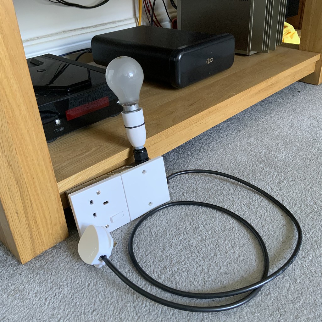
Very silly question...how long should I wait for the bulb to die down?The dim-bulb tester takes the risk out for sure, if there is a transformer or wiring issue the bulb will light brightly and stay lit. No harm will come to the amp. I watch a lot of vintage audio restoration stuff on YouTube (XRaytonyB, D-Lab, Electronics Old & New, Mr Carlsons Lab etc) and everyone uses a dim-bulb tester. Most having ones far more complex than mine using a range of different Wattage bulbs that can be switched in or out to allow less or more through. A really simple one like mine will protect you from error on first power-up though. Expect the bulb to glow fairly brightly for a couple of seconds as the rectifier warms up and the caps charge, i.e. don’t panic if it lights! It will flash and then fade to a very low glow. The voltages you measure with it in series will be a bit down on what is expected, but it will certainly give an indication all is ok. The 6.3V is most likely AC so set the meter accordingly (that threw me with the Leaks initially, I made loads of noob errors as you can tell from the thread!).
Tony, did you bring your Leaks up with just the rectifier in place or did you pop all the valves in and then try?
Very silly question...how long should I wait for the bulb to die down?
Just tried the rectifier on its own and the bulb is first bright and then dims. Only for maybe 5 secs later for the bulb to re-brighten, to full brightness. I heard a tick from the amp, so turned it off..lol.
Thank you for the guidance Tony.
Just tried the rectifier on its own and the bulb is first bright and then dims. Only for maybe 5 secs later for the bulb to re-brighten, to full brightness. I heard a tick from the amp, so turned it off..lol.