You are using an out of date browser. It may not display this or other websites correctly.
You should upgrade or use an alternative browser.
You should upgrade or use an alternative browser.
Meridian 206 CDP ...partial success
- Thread starter Chris Tarling
- Start date
Mike Hanson
Trying to understand...
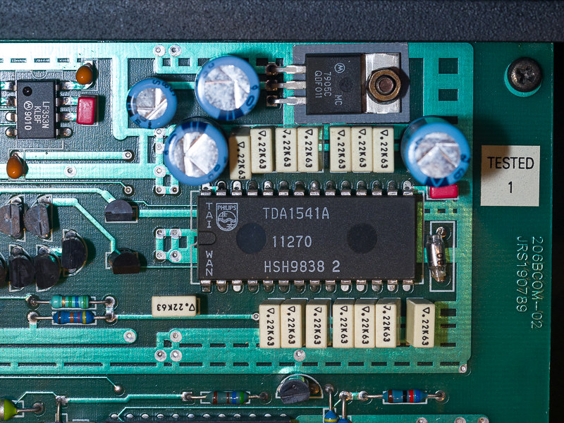
All I can see different to your earlier picture is the LP353N is soldered to the board, rather than nestled in a socket. I guess the same applies to that chip on the lower edge of the image, which is also in a socket in your earlier picture.
david ellwood
Kirabosi Kognoscente
I’m guessing it’s less than regal.
Chris Tarling
Yellow Hound
I’m guessing it’s less than regal.
You got it. This 206 rather surprisingly doesn't have the single crown TDA1541 chip. By serial number it is about 220 units newer than my 206.
martin clark
pinko bodger
Just remember there was only the one production line standard for these days and s1, s2, ( and r1 the lesser) where only binned selections after test from the one line. An artifact of the analogue nature of the 10 bit LSB passive division by emitter-scaling (still quite a feat tbh)
C 1998 that line moved to Taiwan, the process was already old, and there's anecdotal evidence that the result is even unselected chips as the last pic shows, generally met the tighter specification on test band(s) as opposed to late 80s production.
Certainly a decade or more ago @Mike P and I ran between us some simple comparative chip swaps by exchange on that basis against a nos Philips Eindhoven S1 I kept spare. General agreement that feeling messing surrounding circuitry, but /very esp. / the saa7220 supply/ bypass caps , swamped the difference; and late Taiwan production TDA1541A are as good as anything available if you find or need one.
My 2tuppence worth.
Chris Tarling
Yellow Hound
Tried some RS freeze spray on the TDA1541 chip - made no audible difference.
I'm nervous of desoldering the chip. I have a desoldering station but I'm finding that some components take quite a lot of heat to be able to fully desolder the pins.
I do have some 28 pin sockets. My plan, if I can do it without destroying both of the TDA chips I now have, would be to desolder the TDA chips in both 206s, fit sockets and then swap the chips over between the boards.
Is there any way, without having access to an oscilloscope, of testing a TDA chip off-board, say to a basic functional level?
a.palfreyman
pfm Member
Think you maybe need to check #2 machine is working then take some measurements from this and compare / contrast to #1 machine. I managed to overlay the top and bottom images of the transistor section from your photos and add some lines for clarity, but you can't see traces on the upper surface which are hidden under the transistor bodies. Might be useful if you could draw a sketch of these traces, then I could add these to my sketch in the hopes that someone (e.g. Martin) might be able to work out what's-what. I suspect that the transistor banks provide bias current to the TDA to reduce the offset voltage for I/V conversion, but I'm no expert.
I certainly wouldn't swap the TDAs over as you could turn one (potentially) trashed TDA into two...
I certainly wouldn't swap the TDAs over as you could turn one (potentially) trashed TDA into two...
Mike P
Trade: Pickwell Audio
I regularly remove TDA1541 DAC's and have yet to damage one but it does take some practice and you need to be confident in what you're doing.
I suspect the Meridian might be through-plated which makes desoldering much harder.
Chip Quik or similar ultra-low melting point solder is worth its weight in gold* in situations like this.
*Almost literally, it's bloody expensive!
Like Martin said, the non crown 1998 chip is absolutely nothing to be concerned about and could well be superior to the earlier Dutch made S1.
Last edited:
say it as it is
pfm Member
yes everything I have read when researching this points to the vastly improved production methods of the Taiwan being the equal of the S1 and S2


