advertisement


Meridian 206 CDP ...partial success

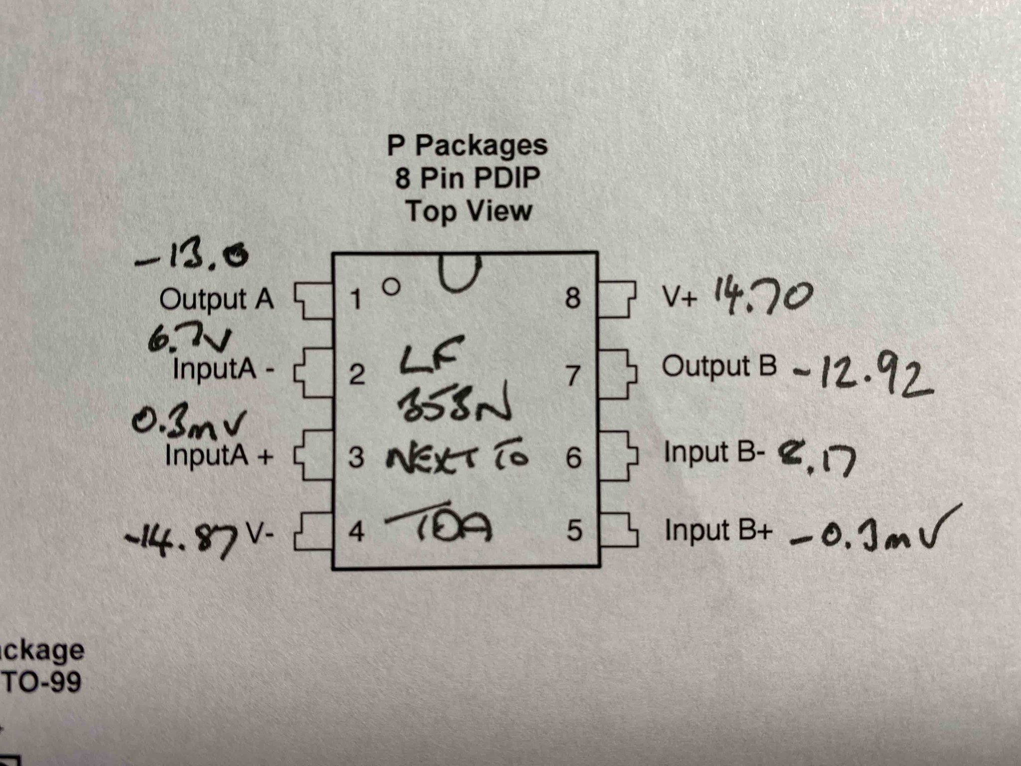
Voltages all seem rock steady.
Although I have replaced the analogue circuit opamps I have only done this in the last few days - i.e. the behaviour I am seeing hasn't changed since the opamp fiddling. Although as I have fitted sockets I can simply refit the original amps.

I don't have dead silence on the analogue output - no ghostly music but some random white noise (perhaps not the best description).

I have a small handheld oscilloscope which might enable me to do something - if I only knew what to do!
 
Thanks all - I am touched by your kindness.

@martin clark I'm going to see how I can get on but might need to call on your help!

Martin kindly helped resolve issues with my Avondale CD3 a few years back (thanks again Martin, ACD3 still going strong). Good chap and seems to know his stuff, he has scopes and everything!
 
White noise could be a dead DAC chip although it tends to come on gradually in my experience. Try cooling the DAC chip with a little squirt of freezer spray whilst listening to the audio output. If the noise clears and music comes back somewhat when the DAC chip is cold that's a sure sign.

It may sound very obvious but have you checked for dry solder joints around the output sockets?

All the solder joints look nice and shiny. I don't like the board mounted phono sockets so I am planning on removing these and mounting some RCA sockets to the rear case chassis.

Incidentally does anyone know a source for these - brass through hole wire tags, either for a spade connector or to solder directly to?

 
Decided to measure all of the pins using my multimeter - results attached.
All of the measurements are steady. Neither opamp feels at all warm.
I found some info on diyaudio that suggests that the voltages I have measured on some of the TDA pins are very low against the spec. Pins 10 through 13, and 16 through 21:
Pin "Spec" Mine
10 -5.2 -3.8
11 -5.5 -4.3
12 -7.5 -3.9
13 -7.4 -4.3
16 -11 -4.6
17 -11 -4.6
18 -7.5 -4.5
19 -7.5 -4.6
20 -5.5 -4.4
21 -5.2 -3.9

I am unsure as to how to interpret these, or whether the info from diyaudio is correct.


[url=https://flic.kr/p/2mPPcHW]
[url=https://flic.kr/p/2mPTMfg]
[/url][/url]
 
The outputs of the opamp next to the dac look all wrong; if that is doing the I/V conversion, the +ve input should be very close to 0v; the -ve inputs exactly the same; and these should exactly reflect the voltages seen on pin 6 and pin 25 of the TDA1541.

The outputs at something like +2v, not saturated to one voltage rail as yours are.

How did the temperature test go?

Can you put the original opamp back in the socket for this one and try again?
I need to hunt down a schematic...

Thanks Martin!
Refitted the LF353N, which produced these readings:


Looks like a swap to the LME49720 wasn't a good move. But then I did it as an experiment and if this is my learning point then it was worthwhile.
 
Thanks for the quick update. I found a couple of decent pics of the innards online,but no schematic yet; and it s not quite enough to work out the area around this opamp and how the I/V conversion is configured,or what the bundle or transistors adjacent are for - so I'm a bit stumped for now!
 
Thanks for the quick update. I found a couple of decent pics of the innards online,but no schematic yet; and it s not quite enough to work out the area around this opamp and how the I/V conversion is configured,or what the bundle or transistors adjacent are for - so I'm a bit stumped for now!

I've looked and looked too - plenty of people asking for a service manual or schematic but no helpful documents.
 
It could just be worth a polite request by email to Meridian, maybe showing a photograph of the serial number.
Manufacturers are often resistant on current designs, but sometimes surprise.
 
It could just be worth a polite request by email to Meridian, maybe showing a photograph of the serial number.
Manufacturers are often resistant on current designs, but sometimes surprise.

I have sent a request - will see if it gets an answer.
Would welcome your thoughts - I know of a used 'fully working' Arcam 70.2 for sale that uses the same TDA single crown DAC. Is it worth me buying this do you think, simply for its chip? I simply don't know whether there's enough indication within my player of a faulty TDA DAC chip.
 
My CD160 (TDA1541, non A type) scematic has voltages for the decouple pins. 7 & 24: -3.5v and slowly get more negative as you go along to 13 & 18: -7.5v but your results could be because the opamps are saturating. Can you trace AOR pin 6 and AOL pin 25 frpm the TDA chip and see if these go direct to your first opamp? If so pull the opamp and push a 1k resistor into each of the opamp pin holes for AOL & AOR, solder the free ends of these two resistors together and to a wire which you need to solder to a local 0v trace. Then play some music and you should get varying ac (up to 2vac but likely a few tenths to 1v) across each of the 1k resistors. You should also see about -2vdc across each of these resistors. That should tell you if the dac is working.
 
Any chance of a good quality photo top side in the dac area to see where pins 6 and 25 go to down stream? Might tell us more with it being double sided in the absence of a schematic. Then at least we'll know if the analogue outs go to the opamp or the bank of transistors.
 
Did you swap out the little orange tants too?

what’s the component that appears to be missing from the top of the last photo?
 
Did you swap out the little orange tants too?

what’s the component that appears to be missing from the top of the last photo?

Haven't touched the orange tants - should I?
The fitting of the the Trichord clock involved removing some components - capacitors I believe. I'm guessing that's the gap you can see.


advertisement


Back
Top