
You are using an out of date browser. It may not display this or other websites correctly.
You should upgrade or use an alternative browser.
You should upgrade or use an alternative browser.
Leak TL/12 Plus / Point One Plus
Tony L
Administrator
That is it, I’ve just whacked a bloody huge resistor on the top so I can barely see it.
I really only want to rework that area once if at all possible. As stated there is no budget here, I don’t care if we replace stuff and the issue still persists, we have at that point ruled an issue out as the component is brand new. My question now is does a 200pF or 300pF cap make more sense in that location?
I really only want to rework that area once if at all possible. As stated there is no budget here, I don’t care if we replace stuff and the issue still persists, we have at that point ruled an issue out as the component is brand new. My question now is does a 200pF or 300pF cap make more sense in that location?
Tony L
Administrator
Did they change the output transformer specs too during its run?
Yes. Output and mains. Mine has the 3900 and 3901 early 300V mains transformer and output transformers (the overwhelming majority of TL12 Plus do). This is the same as the very earliest Stereo 20s (i.e. earlier than my bronze one which has 8778 output transformers).
snowman_al
pfm Member
That is it, I’ve just whacked a bloody huge resistor on the top so I can barely see it.
I really only want to rework that area once if at all possible. As stated there is no budget here, I don’t care if we replace stuff and the issue still persists, we have at that point ruled an issue out as the component is brand new. My question now is does a 200pF or 300pF cap make more sense in that location?
Yes, but only if you add the 4.7kΩ resistor R23 too. See the second schematic, here: http://44bx.com/leak/Leak/Circuits/TL12Plus3.gif
Current mica caps are 220pF and a much better range to choose from.
Tony L
Administrator
Yes, but only if you add the 4.7kΩ resistor R23 too. See the second schematic, here: http://44bx.com/leak/Leak/Circuits/TL12Plus3.gif
Current mica caps are 220pF and a much better range to choose from.
Very happy to add that resistor too if you, Will and John recommend it. To be honest I’m happy to do it in my Stereo 20 too as that only has the 82k (I think) resistor and nothing else. I’m pretty sure that is how it was born, but anything that makes both amps more stable, kinder on valves and more reliable long-term gets my vote. I won’t do it immediately (the TL12s are obviously the priority), but whatever I order I’ll certainly buy enough to do the S20 sometime in the future as well.
Yank
Bulbous Also Tapered
I’ll do the Quad 34 test sometime later this morning as that will hopefully change the operating parameters of the input sufficiently to help test Will’s theory. To be honest I’m inclined to accept Will’s theory as-is regardless as it is the only credible one we have and simply replace C15. If I understand correctly, its role would appear to be to help prevent exactly this kind of instability. Makes sense to me.
As I mention above this is a capacitor I do not want to bother testing due to where it is. If I’m going to rework that area, which I’m perfectly happy to do, I only want to touch it once by actually replacing that capacitor with a brand new one. Those tags are likely the most fragile on the board as they look to have been drilled-out further to accept the two components. It will obviously involve desoldering the big chunky resistor too so I just don’t want to do it multiple times. The schematic says 15uuF, which I don’t understand (is that 150pF?). I also have no idea what this type/genre of cap is called, what voltage I need, whether it is polarised etc. If someone could let me know exactly what to buy and I’ll go grab some!
micro micro farad = pico farad
Tony L
Administrator
The circuit I`ve been looking at gives C15 as 0.00002 or 200 pf in more normal terms. Also in series with a 4k7.
I assume that some differences may be to cater for different versions of the output transformer.
Any chance of some further general discussion on this point? I’m really struggling to understand the schematic as I have no electronics training. What I’m trying to understand is whether C15 is in anyway tied to the output transformer type or just sets a safe operating parameter for the EF86. I also realise the amp has a negative feedback loop, but I don’t really understand how these work (my guess would it would be R12 & C7, but I don’t really know what it does!). What exactly is likely to be oscillating, the EF86 or the whole circuit?
Another thing that puzzles me is why there is so much commonality between so many values around the small signal valves in both the TL12 Plus and the Stereo 20? I don’t get this as there is a substantial gain difference between an ECC81 and ECC83, and an EF86 isn’t even a triode!
I don’t need to know this stuff, I’m just curious. All I actually need to know what to buy and I’ll then solder it in and see if it works! I can see some 220pF silver mica caps at HiFiCollective (where I’d have to go to get a matching Takman 4.7k resistor). I could buy some other mica values too if there is any doubt as to the right answer here (I’ll get some 300pF for the S20). Given HFC’s postage prices I’d far prefer to bung an ‘every eventuality’ order in than have to make several.
snowman_al
pfm Member
In very simple terms, the cap C15 sets the maximum frequency the amplifier can amplify. The cap is across the anode load resistor of the first stage so basically limits the frequency range of the following stages and keeps the high frequency phase change due to the output transformer in check. It is in the super sonic range so has no effect on audio frequencies. Have a read of ''First Stage'' on page 143 of the Firsts in High Fidelity.
Amplifier stability depends on a whole range of factors the output transformer being one, as is lay out, cable lengths, decoupling, feedback etc. Oscillation can be a any frequency sub sonic through to super sonic. It can be a single stage or the whole amplifier 'loop' to blame.
R12 and C7 are the feedback components, they literally feed some of the output, from the transformer, back to the first stage. This reduces the gain of the first stage, also reduces the distortion and improves the damping factor. They are carefully chosen to meet the 'needs' of the output transformer within the audio frequency range. (Often using a square wave input and looking at the output on an oscilloscope to see how faithfully it can be reproduced.)
Regarding the 'different' valves, don't forget the parameters / operating points are set by the design and component choice. Just because a valve can have a high gain it does not have to be used flat out so to speak.
Adding the 'step network' of 4.7ohm resistor and 220pF cap across the anode load resistor R5 won't cause any problems. If you look at the TL12+s that Will did you will see he included them on his re-build. They were absent from the original amplifiers. As has already been noted the step network even appeared on the later Stereo 20s.
As I said the very simplest explanation and other opinions additions are welcome. Alan
Barrymagrec
pfm Member
Any chance of some further general discussion on this point? I’m really struggling to understand the schematic as I have no electronics training. What I’m trying to understand is whether C15 is in anyway tied to the output transformer type or just sets a safe operating parameter for the EF86. I also realise the amp has a negative feedback loop, but I don’t really understand how these work (my guess would it would be R12 & C7, but I don’t really know what it does!). What exactly is likely to be oscillating, the EF86 or the whole circuit?
Another thing that puzzles me is why there is so much commonality between so many values around the small signal valves in both the TL12 Plus and the Stereo 20? I don’t get this as there is a substantial gain difference between an ECC81 and ECC83, and an EF86 isn’t even a triode!
I don’t need to know this stuff, I’m just curious. All I actually need to know what to buy and I’ll then solder it in and see if it works! I can see some 220pF silver mica caps at HiFiCollective (where I’d have to go to get a matching Takman 4.7k resistor). I could buy some other mica values too if there is any doubt as to the right answer here (I’ll get some 300pF for the S20). Given HFC’s postage prices I’d far prefer to bung an ‘every eventuality’ order in than have to make several.
As mentioned before C15 and R23 across the 82K load resistor for the EF86 stage roll off the gain at high frequencies by shunting the load. This reduces the tendency to oscillate at HF caused by phase shifts in the rest of the circuit, particularly the output transformer. Obviously if overdone the response at audio frequencies will be affected but if too little the amplifier will become unstable. This is the reason for the square wave tests so popular in the old HiFi news reviews, the squareness of the output and the presence or not of ringing on the transition gives a good indication of stability.
The " goodness" of the output transformer is the major variable and is one of reasons that the various correction networks differ for different build versions of the amplifier. Major advances were made in magnetic materials during the war which is why Williamson, Leak and Walker amongst others were able to produce such improved amplifiers shortly after the war.
C15 / R23 are not the only components involved, R12 / C7 and R12 / C1 , the main feedback components are also involved, as well as setting the overall gain so there are many variables and I freely admit that the deeper maths is beyond me, especially as my valve theory was 53 years ago and I haven`t worked on valve kit for forty years or so.
There is more to the gain of a stage than the gm of the valve, the current the valve is run at and the consequent component values are also very important and affect the final result.
There is a popular belief that you can reduce the sensitivity of an amplifier such as the the Leak by replacing the high gain ECC83 with a lower gain ECC81 or even lower gain ECC82 - this is not so as the global feedback will take care of this at the expense of frequency response and distortion, even if the valves are operating somewhere reasonable on their operating curve.
I`ve dredged my memory for all the above, if any of it is wrong hopefully smarter people will say so.
Tony L
Administrator
Thank you both, that’s great and makes a lot of sense. It is just broad-brush stuff I’m trying to grasp. I’ll have a read of the Leak book later and bung an order in for some bits last thing tonight.
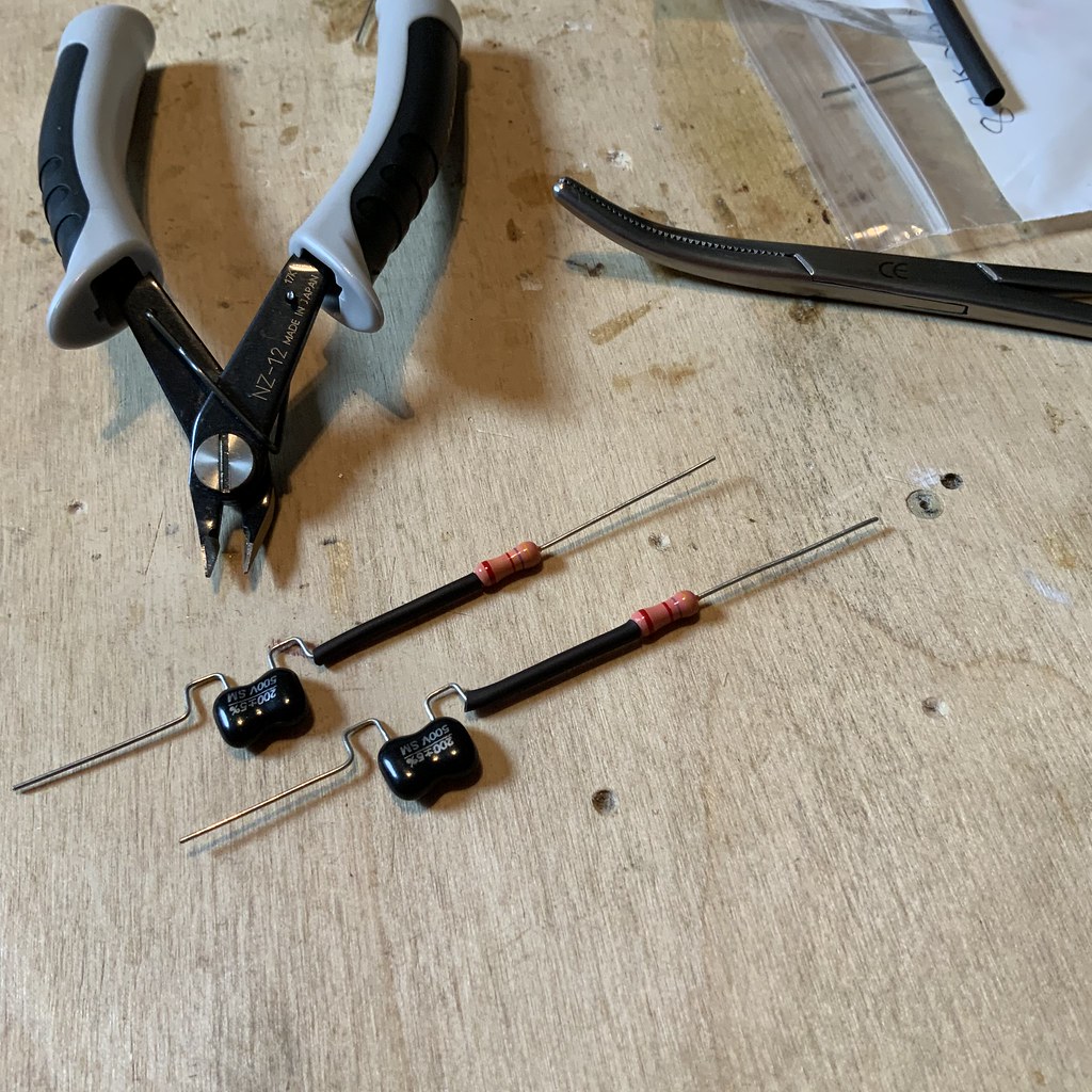
Do these at HFC look ok? There is every value mentioned on the thread to date (15, 200, 220 & 300pF). Maybe get some of each? I’ll get the 4.7k resistors too, I assume half Watt is fine? I only used 1 Watt for the others as the half-Watt are too short to span the tags!
PS I’d like the option to do the S20 too, hence adding 300pF, though I think there is a resistor change there too, at least on Jim’s site the first version (mine) has 100k for R5, whereas the second version has 47k, but neither schematic shows the additional resistors and caps to my eyes. I’ll probably add the 300pF, two more 4.7k and a couple of 47k resistors to the order just to have that option later should I choose to implement it.
snowman_al
pfm Member
Yes those caps are fine. I've had a look and cannot find any axial types unfortunately.
You only really need 200pF (or 220pF) and 300pF values surely. You will not need the 15pF types when you add the R5 and C23 'network'.
As you can get 200pF there is no need for the 220pF as well, or vice versa.
I've had a look back at your bronze Stereo 20 pictures, but just not enough detail to make out the colours of the R5 resistors. Yellow Purple Orange is 47KΩ and 100kΩ is Brown Black Yellow if you want to check before you order.
Tony L
Administrator
Many thanks. The S20 has 47k in place, so I don’t need to buy them!
I thought I’d buy a couple of 15pF just on the off chance this doesn’t work and I wanted to reverse-out. I’ll be looking to put the absolute minimum strain on the tags so will likely cut the existing components to make desoldering more gentle - I’m never comfortable with the forces placed on the other opposite tag that one isn’t desoldering when working on the first end, so I tend to just cut a leg and get the component out in two distinct goes. It’s destructive, but the board is the important bit to preserve here.
I thought I’d buy a couple of 15pF just on the off chance this doesn’t work and I wanted to reverse-out. I’ll be looking to put the absolute minimum strain on the tags so will likely cut the existing components to make desoldering more gentle - I’m never comfortable with the forces placed on the other opposite tag that one isn’t desoldering when working on the first end, so I tend to just cut a leg and get the component out in two distinct goes. It’s destructive, but the board is the important bit to preserve here.
snowman_al
pfm Member
Tony,
Have a look at 'de-soldering braid'. It wicks up the solder from a joint and does not apply any load to the tags. Once the majority of the solder is removed, you can either remove the component or if it still has a little solder holding it re-heat the joint and wiggle the component out. Just a thought.
Have a look at 'de-soldering braid'. It wicks up the solder from a joint and does not apply any load to the tags. Once the majority of the solder is removed, you can either remove the component or if it still has a little solder holding it re-heat the joint and wiggle the component out. Just a thought.
Tony L
Administrator
I do have some. I’m actually reasonably good at desoldering, just a little paranoid as a tag broke when I was doing the Stereo 20, but it had been reworked previously by someone else so may well not have been my fault. I do actually have a Hakko FR301 electric desoldering tool too. It wasn’t a huge amount of use here desoldering the components due to the angles (it’s obviously designed for through-hole boards), but was great for cleaning up the tags afterwards. I did cut most component legs as there was no way I was planning to re-install anything I took out, so may as well go for the easy route. It was the opposing tag I was worried about, not the one I was working, i.e. I wanted to avoid the bending forces on the other tag as I free the first end.
Tony L
Administrator
200pf C15 and 4.7k resistor fitted:
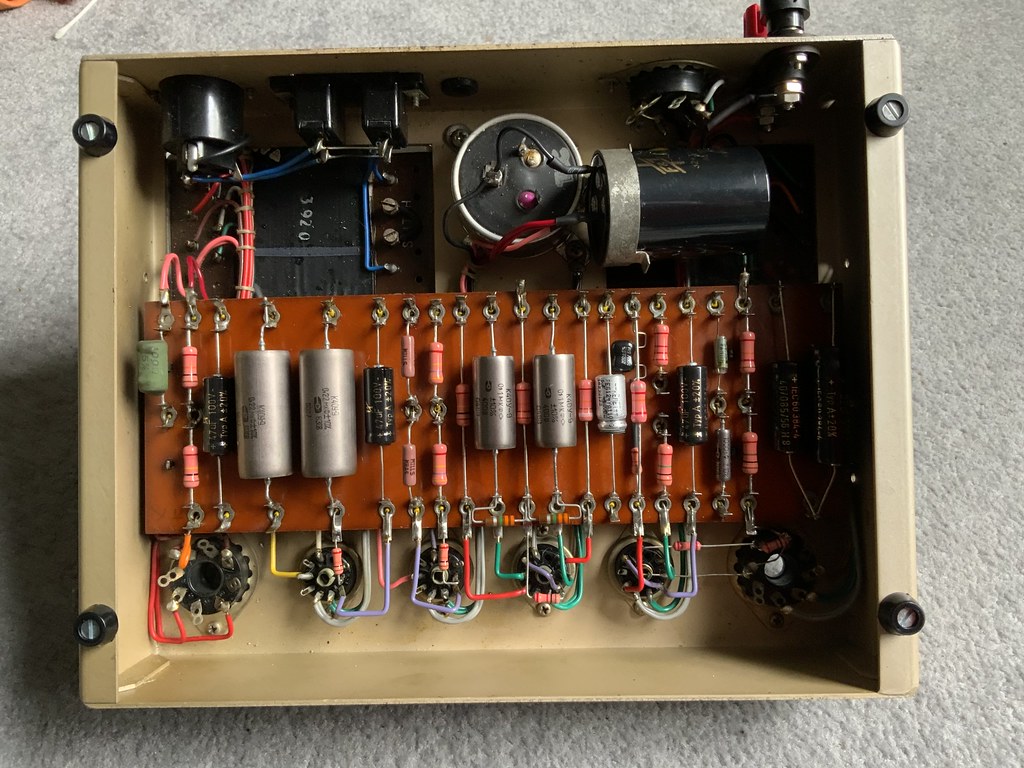
Plus some very nice new speaker terminals from Will.
Annoyingly it hasn’t fixed it, if anything it has made it worse with amp #2 now sounding a little distorted after ‘clearing’ the buzz. Amp #1, which has also had the mods, still sounds fine.
Any ideas?
Plus some very nice new speaker terminals from Will.
Annoyingly it hasn’t fixed it, if anything it has made it worse with amp #2 now sounding a little distorted after ‘clearing’ the buzz. Amp #1, which has also had the mods, still sounds fine.
Any ideas?
Barrymagrec
pfm Member
I think you need to get a scope on it.
Very neat work.
Very neat work.
Radford Revival
Trade: Radford Revival
Looks like the speaker terminals fitted nicely!
Hmm, if it's sounding distorted, that suggests that the unfortunately the amp now may be marginally stable with the new anode network in place. This may possibly be an interaction with another problem though and the blame might not lay squarely at the mod itself. As Barrymagrec said I think it is scope time. Plus I would recommend further testing with a dummy load just in case.
Hmm, if it's sounding distorted, that suggests that the unfortunately the amp now may be marginally stable with the new anode network in place. This may possibly be an interaction with another problem though and the blame might not lay squarely at the mod itself. As Barrymagrec said I think it is scope time. Plus I would recommend further testing with a dummy load just in case.
S-Man
StrivingON
Distortion can occur if the push and pull halves of the output stage are not well balanced. Might be an idea to check the voltage across R19 and R20 are about the same (11V).
My only other thought relates to an earlier comment that the Russian caps are very reliable. I'm not sure which ones thay are in your amp, but maybe it's time to question this assumption?
Thirdly, I agree you need to get the scope out. I suggest posting a pic of the output waveform (across an 8R resistor or a cheapo speaker) during the noisy initial period and ideally with a square wave (1K or 10Khz @ 10mV or so) input to seek out the distortion.
Tony L
Administrator
I do have modern metal-film 3M3 resistors in my stash so can replace them if need be. I’ll measure R19 & 20.
PS If it is unstable and maybe about to fail what is the likely point of failure? At this point the valve set is obviously worth far more than the amp and I really, really do not want to kill a good Mullard GZ34!
PS If it is unstable and maybe about to fail what is the likely point of failure? At this point the valve set is obviously worth far more than the amp and I really, really do not want to kill a good Mullard GZ34!