graham-r
pfm Member
OK, so I wanted to use a Velleman K4700 DC Offset Detection PCB to protect speakers when using my aging Crimson Elektric CS1500 Power amp......
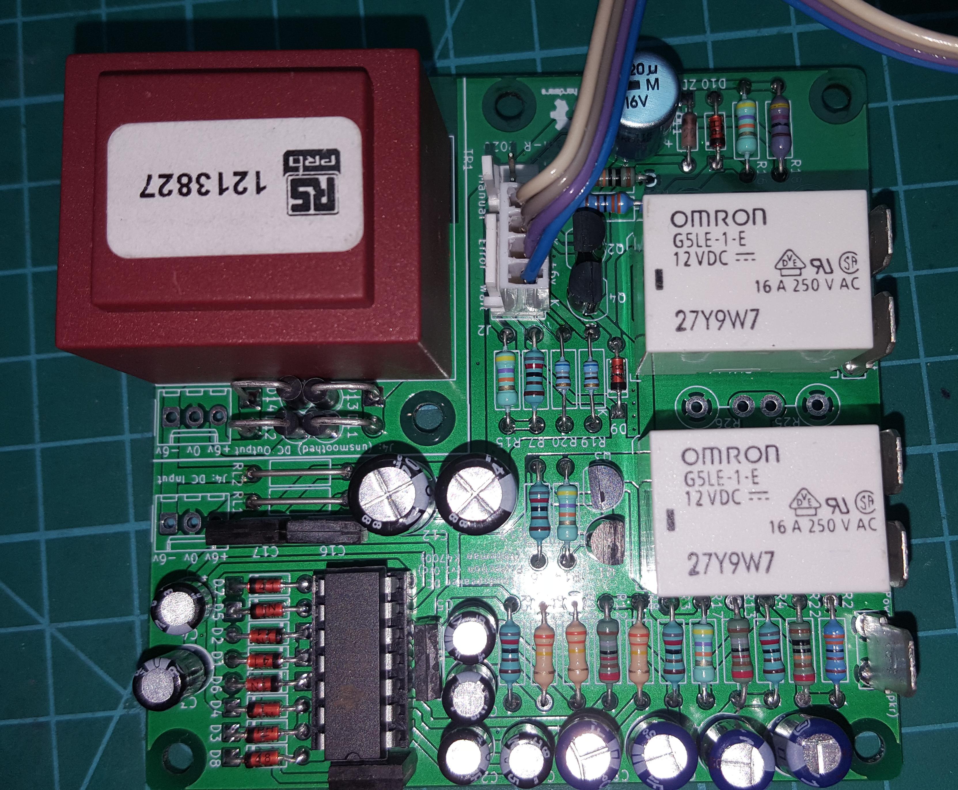
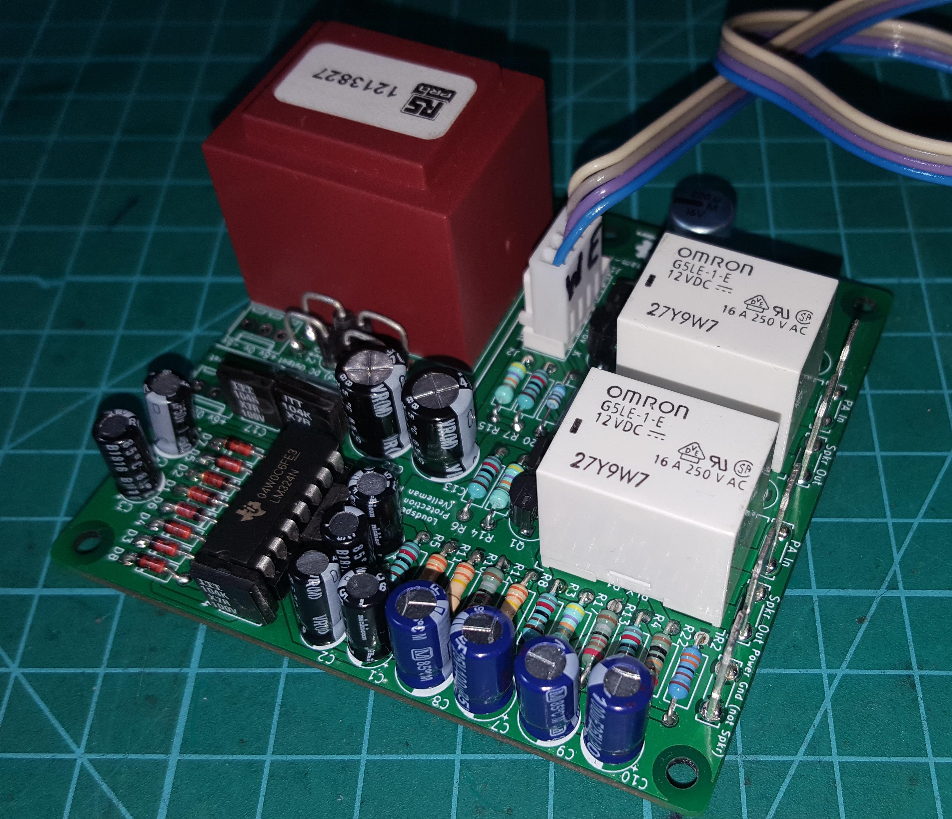
But there was no way the Velleman PCB would fit in the remaing space in the CS1500 as it was too long (approx 125 x 55mm). So, once again having waaaaaay too much time on my hands I made my own version that would fit in the approx 80 x 80mm space available - as well as adding some useful features to make it more flexible.
The schematic used is identical to the one published by Velleman with the addition of four decoupling caps. The transformer and relay 'footprints' and connections are identical to those supplied by Velleman although I used different components (RadioSpares and Omron respectively).
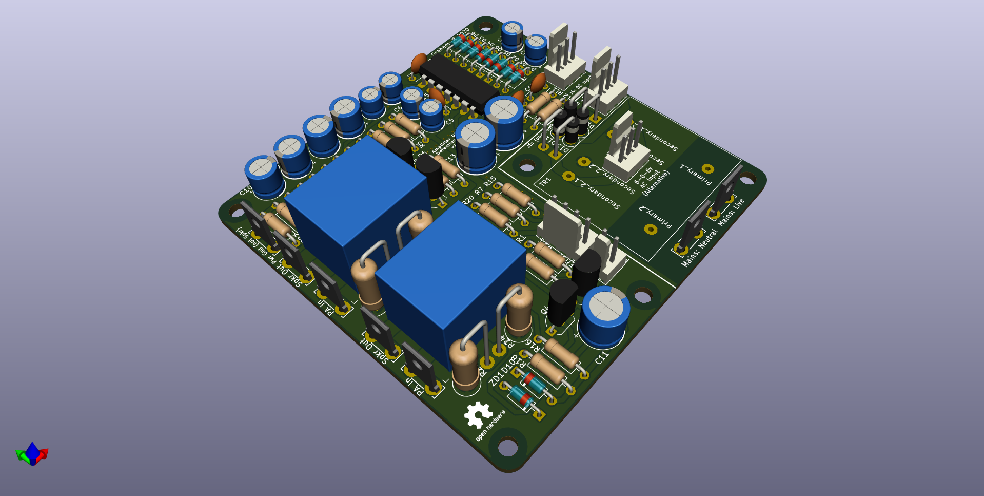
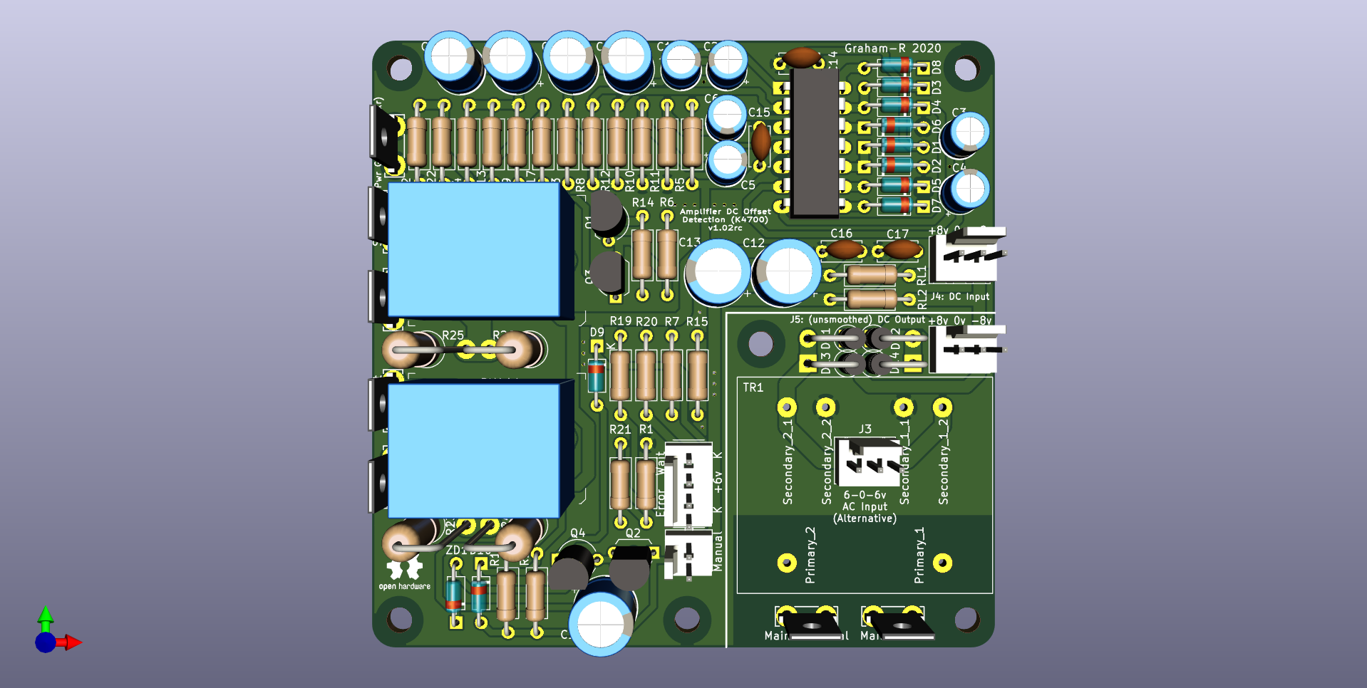
The PCB's above don't show the transformer, instead they show a connector (J3) so an off-board AC supply can be used as an alternative. The entire transformer section of the PCB (with rectifier diodes) can be cut off and placed remotely and connected using a cable between J4 and J5.
External DC can also be connected via J5 (approx +/- 8v).
This PCB above is a slightly revised version to those I had made, electrically they are identical.
I will publish the gerbers on Github fairly soon if anyone else wants to get some made.
But there was no way the Velleman PCB would fit in the remaing space in the CS1500 as it was too long (approx 125 x 55mm). So, once again having waaaaaay too much time on my hands I made my own version that would fit in the approx 80 x 80mm space available - as well as adding some useful features to make it more flexible.
The schematic used is identical to the one published by Velleman with the addition of four decoupling caps. The transformer and relay 'footprints' and connections are identical to those supplied by Velleman although I used different components (RadioSpares and Omron respectively).
The PCB's above don't show the transformer, instead they show a connector (J3) so an off-board AC supply can be used as an alternative. The entire transformer section of the PCB (with rectifier diodes) can be cut off and placed remotely and connected using a cable between J4 and J5.
External DC can also be connected via J5 (approx +/- 8v).
This PCB above is a slightly revised version to those I had made, electrically they are identical.
I will publish the gerbers on Github fairly soon if anyone else wants to get some made.
Last edited: