advertisement


KiCAD: Velleman K4700 DC Offset Detection PCB - updated

The interactive bom and a few other bits are available here, I haven't included any component source info as that is down to preference. I will add RS info for the few components that are not PCB based (spade/Molex connectors) and a howto later.

https://github.com/graham-r/DC-Offset_K4700-Stereo_v1.02

Click on the green box with 'code' written on it and download zip (or clone it if you use git).

Hopefully it should all work......
 
Interesting article here:
https://www.halfgaar.net/dc-protection-with-relays

I think Vellermann must have fixed this. The schematic posted earlier seems to be wired with the speaker connected to the NC terminal which is connected to 0V via 0.6R.
I have a vintage K4700 which doesn't do this.

Thanks for the link.

I think you must be referring to the resistors R23/4 and R25/6 - in two pairs connected in parallel, which is 0.6K (not R) - these are optional and only fitted if the PA PSU is single rail. This is how it is described in the Velleman manual and in the note on the schematic.
 
Yes you are right, sorry 1K2 in parallel with 1K2.

Not sure if 600R will fix the problem with arcing relays or not :confused:. Probaby not.
 
Just put in an order for some Dual/Mono DC offset detection PCB's (and a new dual LT1086 PSU PCB).

If they all prove OK I will post the gerbers on github, I have got quite a few PCB's in the pipeline that may be useful to some so it makes sense to put them all on a separate thread (some when....)
 
Interesting article here:
https://www.halfgaar.net/dc-protection-with-relays

I think Vellermann must have fixed this. The schematic posted earlier seems to be wired with the speaker connected to the NC terminal which is connected to 0V via 0.6R.
I have a vintage K4700 which doesn't do this.
Thanks for that link, confirming my suspicions that a series mechanical relay is not a reliable protection. You see some extreme and complex measures in surge protection devices to try to quench an arc.

The recommended shunt NC connection protects the speaker, but is fatal to many amplifiers if it false triggers.

Mosfet based switches should work in series as they can break high DC voltages
 
The recommended shunt NC connection protects the speaker, but is fatal to many amplifiers if it false triggers.
Mosfet based switches should work in series as they can break high DC voltages.

That seems like the best compromise to me - transistors of the type used in power output stages are cheap, drive units are usually very expensive to recone once the voice coil has been fried.

I had some Spendor BC1's repaired (they were damaged when I bought them !) - the cost was over £200 - that was about 10 years ago now.

Mosfet based switches should work in series as they can break high DC voltages.

Anything semiconductor based also has the possibility that it will fail in a short circuit. Not what you want.
 
As I recall Rod Elliott does PCBs for his speaker protection circuits...
And I think they are quite compact.
Cheers Andy.

One of many suppliers - I made the alternative K4700 PCB for my specific requirements (based on available space) and to practice using KiCAD.

I do have a vague plan to produce my own circuit design that removes the need for the transformer......
 
Anything semiconductor based also has the possibility that it will fail in a short circuit. Not what you want.
The switch does not dissipate power, either ON or OFF.
120V 42A 10 mOhms in insulated TO-220 is about £1, you won't break that easily
 
The next lot of updated stereo and mono K4700 PCB's should be here within a few days, assuming they both test out ok I shall be fitting two mono PCB's into my ancient Crimson amp and a stereo version into a A&R A60 based power amp I am building for my workshop - assuming the PA PCB is OK.

There are a few spares of both types.....
 
The PCB's do look very shiny, I will be able to test them sooner than I thought due to being back home early because of this bl**dy Kung Flu (again).....
 
OK, sorry for the delay, got a bit ill (no, not the flue-like virus !)

I had a second batch of K4700 stereo PCB's made slightly modified with easier to solder transistor pads, this has been tested and works exactly as the original.

I can get it to trigger on 1 volt DC so that is good (I am assuming the -1 volt DC will also work).

The mono version should be tested this week, I will post the gerbers for both versions on github for anyone who wants to order their own.

I have 6 spares of the stereo version, I also have approx 20 spare mono PCB's (but these haven't been tested yet) if anyone is interested.

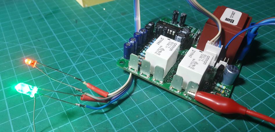
This pic shows the device in 'triggered' mode - by connecting -8v to the speaker in /relay terminal, a similar effect occurs when using the manual mute facility - without the green LED being lit.

Quite happy with the result.
W8VD7Vh.jpg
 
Hi Graham, I’m currently working on a pair of mono blocks and would be quiet interested in a pair of your mono boards.
A board that is smaller than the k4700 would fit more easily for my application.
Let me know what you have in mind
Regards
Mark
 
Hi Graham, I’m currently working on a pair of mono blocks and would be quiet interested in a pair of your mono boards.
A board that is smaller than the k4700 would fit more easily for my application.
Let me know what you have in mind
Regards
Mark

Mark

I have no spare mono pcb's, the post above should have read 2 spare and not 20 !

I haven't tested them either due to me being rather unwell, everything is on hold.
 
I find this very interesting. I have built a ebay UPC1237 pcb. Chinese of course. Well the pcb tracks were tiny, the pads tiny and to cap it all I was not happy with its "slow start". It was certainly not what I would call slow not did it seem easy to extend (I would like at least 10 seconds so everything is settled nicely). I was minded to purchase this Velleman kit from Rapid Electronics as I have some more parts to get from them for another project. Reading the above I am now not so sure. The Velleman kit does seem overly complex although if it does what everyone wants thats OK. I would certainy be interested in buying any pcb's that are being sourced from China. In my experience pricing is such that buying 20 is not much more costly and 5. I make my pads and tracks etc. quite large so things are serviceable - but then thats me.I have also ordered the 6 transistor slow start also advertised on ebay and it gets good reviews on Diyaudio.

BTW I am building a balanced JLH twin power supply amp. My Tannoy Golds dont need lots of power and class A suits me fine.

Andy
 
Very easy to change the turn-on delay with UPC. Just increase the value of the cap on Pin 7.

10 seconds is a very long time for solid state to "settle"!
 
Well the cap is already 100mfd. I will check the resistor though. However, I was not at all impressed by the pcb itself.

Andy


advertisement


Back
Top