advertisement


Connoisseur BD1 kit project circa 1973

Hi Craig,
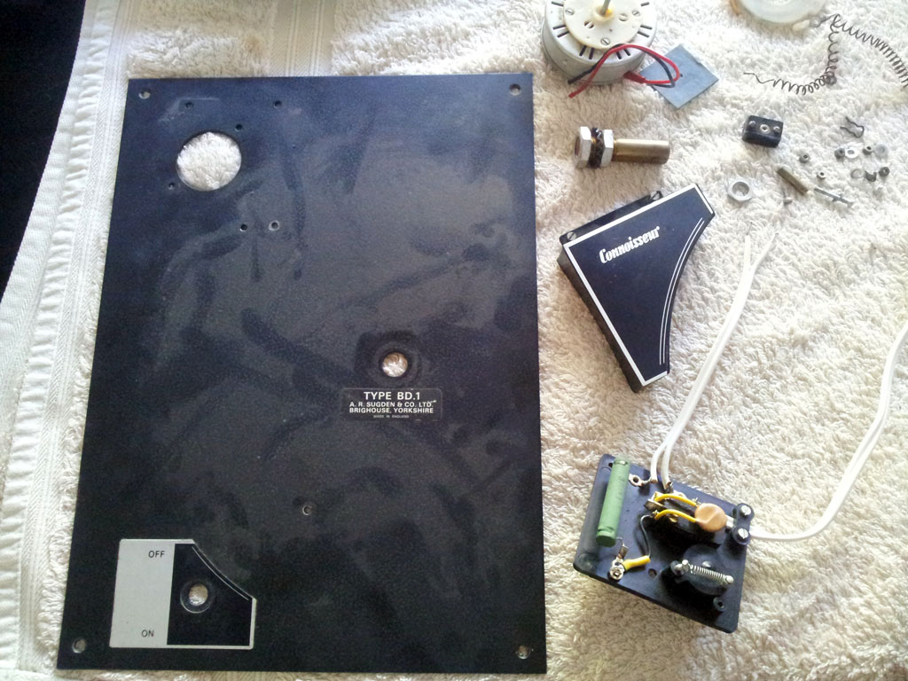
you say in your post "..the latter of which provides motor grounding and holds the plastic cover of the junction box on." I've been wondering about the earthing/grounding situation as it only has a 2 wire supply cord , live and neutral (blue and Brown) from the wall plug. Was the grounding path supplied via the tonearm cables and possibly the person putting the record on. 110v in the States is not too bad but UK's 240v could have Grandad popping his clogs.

Alan.
I suspect that it all passed double insulated two-wire safety standards of the day, but, yes, the grounding scheme has more to do with avoiding hum induction than with reducing the 'potential' for electrocution.
Looking at the first picture in post#15 I see a brass screw head between the on/off switch and the platter bearing, what does it do. I have a hole but nothing to fill it.
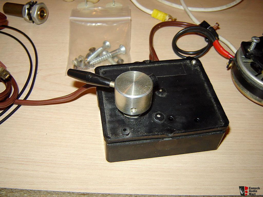
That will be your combined on/off switch/power supply mounting screw hole. Along with a ring nut that goes round the collar of the switch, these fasten this assembly to the motor board.

Calling it a power supply is a bit of a stretch, though. On the UK version there exists but two components, a big power dropper resistor along with a small switch suppressor. There is no need for a phase capacitor with the single phase motor, hence the on/off switch also doubling as a clockwise rotation push mechanism.

1022144-connoisseur-bd1-bd2-turntable-kit-parts-project.jpg
 
Last edited:
BTW, Alan, apparently that plinth pictured in post #15 was by a fellow in Melbourne named Alex Encel. These are described as being of 'real timber'.

Here is another with a lovely Grace tonearm on...

1274086642251.jpg
 
Last edited:
I could go for one of those. When the platter is in place you don't see much of the steel motor board, I was hoping to get rid of all of it, this is only a test run and the 18"x12" cutting board I got is not big enough to take the motor board. So that's one thing I have learnt, go big. I have a router but have only used it once so I'm not ready for a good piece of wood yet. I don't want to go carving willy nilly through 200 quids worth of some exotic wood. Maybe I should take a spare leaf out of the dinning room table, my wife would never know until Christmas and that is a time of good will to all men, or am I just kidding myself.
 
Can any one put me on to a good source for a BD1 belt. The old one looks good but I would be happier with a new one and the old one for a spare. Also I don't have an "O" ring to correct the motor's misalignment caused by the pull of the drive belt, any suggestions?

I had the router out today, first time I've used it for more that 8 years and then I only used it once. It's a scary thing to use but I didn't destroy anything and I didn't lose any blood so it must have been a good day.

Thanks Alan.
 
I just cut and pasted this from another website where I had psted it bearing in mind I am in the USA, got any ideas?

Connoiseur BD 1 Motor problems

Post by acass » 03 Jun 2021 12:00

I am in the middle of building a Connoisseur BD 1 Turntable. I bought an old BD 1 Kit Turntable and was putting it on a new plinth but when I tried the motor I found it no longer runs. I checked across the motor leads and found an open circuit so my project is at a halt. I checked the voltage at the outlet 125v and after the on/off switch on the deck, 0.59v in the on position and 0.29v in the off position. Looking inside the box containing the switch I see it's a 2 stage or 2 pole switch with a large resistor and 2 orange caps, doing what I don't know. My unit was made in England for the American market so I'm not sure how the change from 50Hz to 60Hz or the voltage was handled. If you have any knowledge of a Connoisseur BD 1 set up please help, in fact if you have any useful knowledge please help.

1) Can I buy a new Connoisseur motor if so where?

2) Can the old one be rewound if so where in the USA?

3) Can a substitute motor be used?

4) What are my options to keep this project going?

Thank You.

Alan Cassidy.
Hello Alan,

The circuit has two tapping points after the switch; one for 200/240VAC operation, the other for 100/120VAC. The latter bypassing the 3.7kOhm 10w resistor which drops the voltage by half.

The orange components are likely to be switch suppressors. Typically there is only the one necessary. Perhaps they doubled up two to get the value they wanted? There is unlikely to be a capacitor present, as the motor is single phase and won't benefit, hence the power switch doubling as a 'push it in a clockwise direction knob'.

What you'll want to check here is that the short output lead from the switch goes direct to the 100/120VAC terminal, bypassing the large resistor. In the photo below, the short black insulted lead (with the yellow insulated ring terminal connector on) need be moved to the terminal hole that is top left between the large green resistor and the LH white insulated leg that goes on to the motor junction box (yes, you want to feed the motor the full 100/120V).

BTW, I'll ask my mate James to pull out his spares box and check for a motor tension band to measure up for you.

Craig

7054747089-c4593c44c3-o.jpg
 
Last edited:
Thanks Craig it's very much appreciated. Reading between the lines it looks like the motor has always been 110/120volts no matter which country it was sold in. I think my MultiMeter needs new batteries or I need to go on a refresher course or perhaps I used the wrong settings. I'll go back and recheck my findings.
 
I've got it running. Because I didn't want to router too much out of the board I mounted everything on I took the backing plate off the switch and that allowed the inside of the switch assembly to flex stopping the cam from fully depressing the top little red button that activates one of the switches. So I put a wedge under that corner and now it works. As this is only a test piece when I make the final one I will know what to do.
 
Ok, you are scaring me now!

There are tried and true safety related reasons why things like mains switches have things like back plates, none conductive covers, etc. on.
 
I replaced the big black metal mounting plate/board and mounted all the individual parts to the bottom of a 3/4" Bamboo cutting board which is non conductive. The parts with a shaft on ie: motor and on/off switch I had to router a hole to drop them into so I had sufficient shaft sticking out the top side to mount the drive pulley and switch knob on. No electrical parts are exposed so no chance of a shock, I even put a 3 amp fuse block under the deck fed with a 3 wire lead and 3 pin plug.
 
Way back when, in the first few posts of orig thread, I’d posted these scans from a couple of then-ancient, small-circ UK mags I’d hapened-across:
http://www.acoustica.org.uk/misc/ARSugden.zip

turns out the author was member ‘eguth’ here, and he took /great/ (and rude) exception to me posting them, even though they were, back then & to allintents & purposes, given-away-free. And not necc of any use even so; certainly not proprietary.

Martin

Your link does not work (for me). Nor can I get access via the webisite you cite. So I can't check whether we are on to the same thing.

I gave free access to my BD1 series published in Audio Conversions magazine until I withdrew the copyright permission. I had to do so because of abuse by some. When you say "certainly not proprietary" this ignores the possibility that a copyright holder may iniitially grant a free license, and later revoke and start a commercial operation using the copyright.

Posting the articles, or links without permission, is not proper given that the license was publically withdrawn: and is still in copyright.

Thereafter, demand continued. I did sell some copies for a while at near cost. You are, of course, entitled to your opinions about Audio Conversions magazine and my series on modifying the BD1. However, these publications attracted considerable interest - and much praise.

I expect better from your goodself.

Kind regards,

Eric (eguth)
 
The Connoisseur thread has not closed. It has two parts. To get to Part II, Search: Sugden Connoisseur- lost classic (Part II). This brings Part II ONLY. The last post in Part II is #197 (2020). If you are not a member of pink fish media, you may not be able to SEARCH- but I am not certain. Join!

To get to the LINK to the thread go down the items resulting from your search until you come to the only one that has a very light shade of grey name in the extreme right hand side saying "Thread". All other items, at present, say "post".

To get to Part I of the thread, go back to the FIRST post in Part II. There you will find the link to Part I.
 
I had one of those when I was much younger. Can't recall whatever happened to it, but as I don't think that I've ever sold any hifi,bit may still be lurking around somewhere.
 
post #118 on the Part I thread (posted Dec 10,2009 by Tony) is put here to clarify...

"<moderating>
I have removed two posts linking to a scan of an article from user 'eguth' due to a formal complaint regarding copyright infringement from that same user.
Tony"

post #125 (extract) also put here to clarify...

"martin clark
Thanks for providing scans to those who ask for one.

eguth"
 
Perhaps the thread title should be changed to 'Sugden Connoisseur - lost classic? (part III)'?

Nope, just checked, seems there is room for 23 more pages of turd polishing within part II.
 
Last edited:
@acass,

I've just heard back from James. Apparently, he didn't retain the motor tension band, opting instead to glue the motor to the underside of the metal chassis via 3 dollops of silicone caulk.

Funny enough, I recall him complaining that his drive belt started derailing quite frequently around this same time period. :rolleyes: Naturally, my subsequent attempts to describe how he had painted himself into a corner with silicone caulking fell upon deaf ears.

In the absence of assistance from others, suggest you buy an assortment of O-rings and experiment for yourself. I'd start with hanging the motor and measuring the distance between the hook faces whilst tilting the bottom of the motor toward the platter spindle. This should give you an idea of approximate O-ring diameter. You'll want it to be fairly stout i.e. a thickish cross-section; the picture back in post #18 should help here. Note that this was taken with the metal chassis lying upside down with the belt off, leaving the motor being drawn toward the platter spindle by the tensioner. The correct sized O-ring should do the same, that is, until the drive belt is fitted and draws the motor spindle straight up parallel to the platter spindle.

Also, although it isn't mentioned within the user manual, the black plastic ring clamp that goes round the motor housing, which includes the tension band hook, doubles as motor azimuth adjuster. IOWs, this can be loosened and repositioned vertically in order to fine tune motor alignment. Very useful when a drive belt becomes a bit too loose to counter the tensioner, or when a new aftermarket belt is so tight as to not be sufficiently countered by the tensioner - which is how I discovered this adjustment possibility. After all, why would such a talented self-taught engineer like A. J. Sugden* have bothered to have such a clamp produced in the first place? Certainly not just to have a hook hanging off the side of the motor housing.

Craig

* Not only did A. J. Sugden start producing turntables in the late 1940s, he developed what would become the main competitor format in the race to produce stereo record cutting.
 
Last edited:
I had a root around in my plumbing bits and found a suitable "O" ring which only took me 3 tries to anchor in the right place. The drive shaft now sits perfectly upright when running but I have not been able to play a record yet as the arm is still being rewired and serviced.

Yesterday I picked up a solid piece of Maple 20"x14"x1 5/8" and have marked it up for the pockets I am going to router out for the Motor and the switch assembly. The project has been put on hold as I am waiting for for a
1f449.png
/woodpeckers-auto-line-drill-guide so I can get all the holes plumb. When I built the prototype I found my home made drill press/stand drill was not 100% accurate so I'm hoping a factory made one will get my efforts passed by my quality control.

I intend to finish the Maple with Tong Oil if I can wait the weeks it takes to apply and cure. If the whole job turns out well I may spring for a nice chunk of Curly/Tiger Maple. Then again knowing me it may end up with all the other half finished projects. If I have to wait months for the Tung Oil to cure and dry between coats I could well be involved in something else by then.


advertisement


Back
Top