advertisement


Best CD clock upgrade?

As there are a few CD3.5 threads running I decided this was the most appropriate place for this post.

I have had a Tent XO clock for over 2 years and I am now finally finding a bit more time to read the forum and also get round to fitting the clock in my 3.5. Trouble is, the power supply options question is not clear cut to me but there does seem to be building a fair body of experience with 3.5s and Tents.

I have read what I think are the relevant threads/posts and I can see that the main methods with a Tent are:
1. Tent supply on its own
2. Tent supply fed by SR
3. Flea-power regulator
4. SR on its own.

I can't see if anyone has done any comparitive listening with different methods of powering. I may well have missed them and if there are any such reports, would any kind person please point me at them.

I am currently considering either the flea-power or a SR directly connected to the Tent XO.
 
Eric,

Just to show I don't always push my own stuff, I'd recommend you try the 'flea-power' regulator of Martin's.

It's a more optimal solution to this problem - it has lower LF noise and wider bandwidth in a way that matters for this application. You could implement it on a super reg board with a bit of hacking, or dead-bug over a simple copper ground plane with careful layout.

My clock PSU uses a super-reg modded to do 5V and the AD797, but that's not necessarily such an easy task, especially if you don't have a 'scope, as stability with the AD797 isn't so easy. Martin's circuit is simpler which makes stability easier to acheive, since there's less stuff in the loop to mess up phase margins. The supply I did hits my measurement noise floor at >1kHz (under load) and only rises marginally below this.

Don't miss out L1 either...

...and make sure there's a good HF (i.e. SMD, or leaded ceramic / small film) bypass directly across the Tent XO's power pins.

Andy.
 
Whilst I'm at it, here's some info on the Superclock mods...

The basic circuit is competently designed and uses a good low phase noise (series resonant) circuit for the crystal oscillator, with crystal current picked off by a common-base transistor circuit.

This is then squared and sent to a final o/p stage.

The primary circuit blocks are therefore: -

1. Input filtering (choke + cap)

2. Voltage reference (LM336-2.5V) with decoupling locally (Black Gates + Ceramic SMD bypass)

3. Regulated PSU (LF347 Quad op-amp) with all 4 stages paralleled

4. Crystal Oscillator

5. Squaring circuit

6. Final output drive stage

The areas for initial improvement are: -

a. Filter reference voltage

b. Improve supply filtering

c. Add some series R to the circuit output

So, to do the mods, here's what to do: -

a. The reference is sent directly to the op-amp inputs and filtering this with something like a 51k / 1u film cap (must be low-leakage type, like film) improves the wideband noise of the raw supply by around 15dB. You have to fit the 1u between the op-amp 0V pin and the input, and add the 51k in series with the reference feed (cut track, fit R in series, SMD R ideal for this!).

I din't like the paralleled op-amp idea as there's no current sharing R's on the op-amp o/p's - I'd have use each stage for a seperate circuit element (but that's not easy to change), but it works, so let's not 'fix' it.

b. The low noise supply is then LC filtered, before being split into 3, with 3 more LC filter stages to feed the clock oscillator, the squaring circuit and the o/p stage.

The caps on the LC filters can be usefully raised in value to further improve the filters LF performance, I used 220u Rubycon ZL's, with the final o/p stage having a 220u ZL and a smaller (i.e. better HF performance) Oscon, in addition to the local ceramic bypasses.

c. Add a small value (27-50R, might be worth experimenting) between the output logic gate and the output pin. An SMD R is the only option here, just cut the track and solder it across the open section.

The board looks something like this: -

Superclock_II.jpg


The effect of the filtered reference on PSU noise is: -

Superclock_II_1.gif


The effect of the large caps on the circuit supplies is: -

Superclock_II_2.gif


The output is a nice clean, low jitter waveform, with no ringing or overshoot to be seen (if probed properly, hence the coil of wire on the o.p. ground - it's to hold the probe ground with a very low inductance ground path, not part of the circuit!

Andy.
 
Andy,
Thanks for clearing my dilemma. I now have clear path to follow. For L1, I assume you mean the bead that comes supplied with the XO, this is shown clearly on Hacker's (Carl's) useful picture?

It seems that Carl has used vero for the supply with a separate board for the XO and Martin a single board. Can I ask if the layouts are to hand and you don't mind sharing them?

Thanks.

Martin, congratulations and well done on your acoustica site; it has matured into a very useful treasure trove :)

PS I still prefer Ardbeg
 
Because it sounds crap.

I did try that circuit in the 3.5 and all the bass dissapeared. Even using a boring, 'noisy' 317 with its much lower output impedance at LF brought it back. IME it is LF noise (impedance) that creates problems - since it translates directly into LF jitter, and the result sounds... odd. I have a hunch (which I can't test) that this is much more of an issue with bitstream dacs like the 3.5's than with multibitters though, since bistream has all sorts of sensitivities to clocking over and above 'proper' dacs.

Eric - I'll post a pic of the reg later
 
Hi Eric

I used vero board as a test, really. It's up and working with a NE5532 opamp, but I have designed a circuit-board around the AD797 that I plan to put into place soon. I've got my AD797, but I made a balls-up and ordered the SOIC, not the DIL so I need to get an adapter before building the circuit.

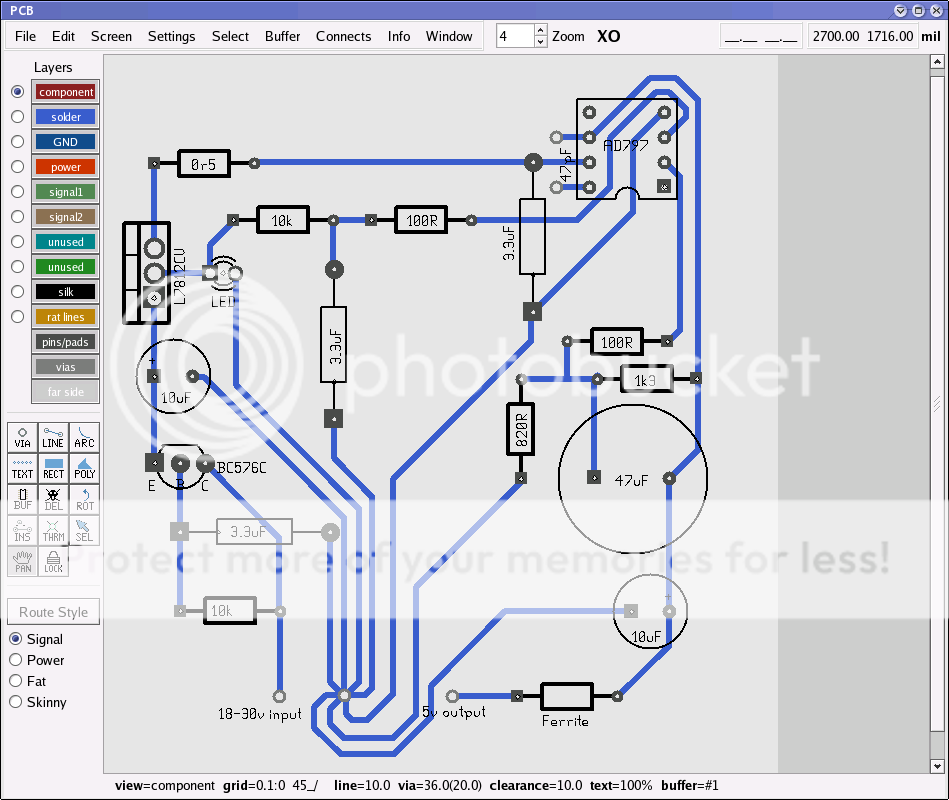
XO-psu-PCB.png


I also wonder if that's the most efficient way to build it...? Any insight?
 
martin clark said:
Because it sounds crap.

I did try that circuit in the 3.5 and all the bass dissapeared. Even using a boring, 'noisy' 317 with its much lower output impedance at LF brought it back. IME it is LF noise (impedance) that creates problems - since it translates directly into LF jitter, and the result sounds... odd.

Hmm, I can't think how low impedance at audio frequencies will have an effect - the XO is working well into the MHz range. If any LF noise is getting through from the 7808, it should be possible to filter it out by setting the roll-off point of the filter low enough.
 
I know, it flies in the face of expectation, but I spent two weeks and over 20 iterations of layout, turnover freq and decoupling all trying to get it to work as well as a bare 317 and gave up...!

Ouput impedance of Guido's filter is about 4ohms. It really does seem to matter.
 
Noise will be very low, as will impedance at the frequencies of interest.

But not as low as Martin's circuit, at the real frequencies of interest.

Hmm, I can't think how low impedance at audio frequencies will have an effect - the XO is working well into the MHz range.

Therein lies the answer - think phase noise, think spectra, think what's most important in terms of jitter and it's audibility ;)

The only relevant part of the circuit that's going to be actively reducing supply noise in the MHz range is the local bypass capacitors, the active circuit is irrelevant up there, which is why I reccomend the choke, since it will decouple the high-Q cap needed for a good local bypass from the regulator and allow both the reg. and bypass to work optimally.

I could offer some measurements of the supply noise of the PSU on Guido's XO-DAC (which I assume is similar) vs. the AD797-based circuit, suffice to say the AD797 circuit is around 5dB quieter above 2kHz increasng to around 20dB quieter at LF.

Andy.
 
Carl,

If you haven't built that PCB yet, can I suggest re-locating the 3.3u across the AD797's rails to the end of the AD797 and using a 5mm pitch polyester film (Wima MKS2 for example) with shorter tracks running parallel to each other and to the relevant pins of the device?

The AD797 needs good local decoupling, those traces and the cap are likely to have quite a lot of inductance which might affect stability.

Consider also whether you can re-locate the 47u across the 1k3 the other side (i.e. between the op-amp and the resistor) since this is the HF path and would benefit from shorter traces to the AD797.

In fact, since you've done most of the hard work, if that PCB package is free and you can send me the layout file if you'd like and I'll give it a 'tweak' for you and you can all learn something in the process (unless it's a 'Apple Mac' thing, in which case you're on your own ;) ).

Andy.
 
PS I still prefer Ardbeg

Now there's a malt with real character!

It's one of my fave's too, but I have a nice selection here at present I'm working my way through, Dalwhinnie is very different, soft, almost flowery compared to the almost astringent extreme peatiness of Ardbeg.

Mmmmm...

Andy.
 
Andrew L Weekes said:
Carl,

If you haven't built that PCB yet, can I suggest re-locating the 3.3u across the AD797's rails to the end of the AD797 and using a 5mm pitch polyester film (Wima MKS2 for example) with shorter tracks running parallel to each other and to the relevant pins of the device?

The AD797 needs good local decoupling, those traces and the cap are likely to have quite a lot of inductance which might affect stability.

Consider also whether you can re-locate the 47u across the 1k3 the other side (i.e. between the op-amp and the resistor) since this is the HF path and would benefit from shorter traces to the AD797.

In fact, since you've done most of the hard work, if that PCB package is free and you can send me the layout file if you'd like and I'll give it a 'tweak' for you and you can all learn something in the process (unless it's a 'Apple Mac' thing, in which case you're on your own ;) ).

Andy.

Great ideas, and I'll enjoy learning from this. The PCB program is for X-windows systems only, so that means no MS Windows, I'm afraid. Linux, FreeBSD, OpenBSD, NetBSD, Solaris... all those will probably be fine, but none of Bill G's evil software ;)

If you've got a linux box kicking about I'll post the files, otherwise I'll have a bash at it myself.

Thanks Andy

Carl

PS. You ain't lived until you've tried a Bunnahabhain :D
 
I've got Linux-on-a-bootable-CD somewhere, just no idea beyond getting X up and then it all goes to pot...

...looks nice though ;)

Andy.
 
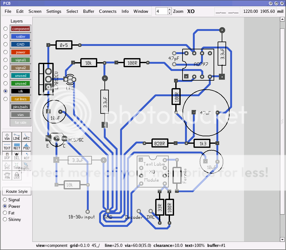
Ok, here's a revised version. I've still got the 3.3uF BC/Vishay film across pins 7/4 of the AD797 for decoupling, just with shorter parallel tracks. I've compressed the circuit a little, too... this leaves room for putting the Tent XO module on-board which brings other obvious benefits.

XO-psu-PCB2.png


As always, comments/suggestions/improvements are gratefully received. I'd love to get this to the stage where it's ready to produce samples with an etching kit, test it (preferably with a 'scope, which I don't have) and then build a final version for use in my cd3.5.

If there's enough interest, perhaps we could have some boards done professionally?

Cheers,
Carl
 
Is there a reason why you don't put the GND in the middle of all that unsued space? To me, it looks like you could usefully shorten your ground return paths.
 
Carl,

Can that package handle a copper ground plane on the top layer?

for this application, a ground plane would work well, since if you keep the 0V star connection in a nominally similar position to your existing star point, the return current flows are well defined.

The advantage is for the high frequency stuff (i.e. the clock) it will give a much lower ground impedance - I like the idea of implementing the Tent XO on the same PCB, but currently that 0V return track is quite long (electrically) and inductive.

If I get a mo today, I'll sketch out the idea...

Andy.
 
Unfortunately, I don't think it can handle a ground plane. Any suggestions for a (free) program that can? Eagle? The only problem would be importing the stuff from PCB, unless it can read gerber files.

Markus, it's funny you should mention that because I'm re-jigging the ground layout at the moment...


advertisement


Back
Top