advertisement


A thread for discussing the science behind power cables and their potential influence on amplifiers

There is nothing technically wrong in the vid. I agree that the acronym is marketing bollox.
It's not just Ohm's law, what about inductance?

Your last two lines are technically wrong - you need to add the word "peak" in there somewhere, otherwise you're just as guilty as Conyata at distorting the facts.

My theory is a that it's the earthing/grounding of components that is affected by mains and signal wiring changes. However, Naim claim that they fit large, low impedance, transformers to shorten conduction angles and this results in better sound (IIRC they say this is due to sensitive audio circuitry being "connected" to the noisy mains for a lower proportion of the time). If that is true then lowering the impedance of the mains lead might lead to better sound.

WRT your amp only needing 0.6A - maybe you have high inductance in your supply, or in the amp itself? Maybe it's got a high impedance transformer and small smoothing caps? Some AV amps use a high rail voltage but with loads of voltage sag as a cost effective way to achieve the power ratings.


I'm afraid it's totally technically wrong because they are attributing incorrect cause and effect. Conflating one thing with another. Its the worst kind of deceptive marketing imo because it sounds plausible to the technically ignorant.

As I said they are either technically incompetent or con artists.

Omg, how can you possibly say I am as guilty as shityata of distorting the facts. Yes I missed the word peak out. That's a simple ommission not a deliberate attempt to mislead or an indication of technical incompetence....and yes I am fully aware of the difference between impedance and resistance.

OK you have a theory about grounding. Now come up with some facts that show how it actually affects sound quality.

My amp only draws a peak of 0.6 amps because that's all it needs. It is not detrimentally restricted by the mains supply or the mains cable. The design works well and sounds fine. Come on, think about it for a moment. Driving speakers to say 64 Watts (maybe 103dB with 85dB/watt sensitivity speakers) how much current do you think you need? Even with horrible phase angle 2 ohm speakers. Just do the maths.

Also, why do you think the musical transients don't show up on the mains current waveform? Possibly something to do with the reservoir caps supplying what is needed.? ;) Again it's down to proper psu design in the component and the amp circuit design which should have good rejection of psu fluctuations. If your amp is changing sound with mains cables it is categorically a shit design, or your impression is a product of flawed uncontrolled sighted comparisons.

It's no good saying maybe this or maybe that, you are just trying to perpetuate your beliefs instead of using factual information.

I'm sure you can find amps that draw more, but don't for one second think it's 100s of amps related to the musical transients. This was just an example to show people what is really going on as opposed to the marketing bullshit many are all too ready toswallow.
 
Last edited:
There's nothing I would worry about regarding "only" 0.6A peaks in the mains lead (i.e. the primary side of the mains transformer).

The area under the peaks (actually their equivalent at the transformer's secondary side) is simply the charge needed to replenish what the amplifier took out of the reservoir capacitor during the remaining portion of half a mains cycle.

The peaks do drop with greater inductance in the mains supply but they widen to make the total charge the same.

Numerically, 0.6A peak is about right for a stereo amplifier having a +/- 40V supply with 10,000uF reservoir capacitors and consuming about 10W per channel (most of which will actually be idle power at reasonable audio levels).

Thanks, this is spot on.
 
.


.

can you go into a specific example of a psu imperfection and how it is corrected by a mains lead?


I'm afraid that you may have to wait a long time for an answer. They don't like answering questions ( raised by points that they have made ) that challenge their faith.
 
OK you have a theory about grounding. Now come up with some facts that show how it actually affects sound quality.

I don't feel motivated to do this. Perhaps that's something to do with the tone of your posts?
 
Ironic that some of you have so much faith in your engineering knowledge.
What's ironic about it?

Its not faith. Its factual knowledge that comes from education, training and experience in the subject matter.

Unless you want to start contradicting engineering and scientific knowledge of course. Good luck with that.
 
What's ironic about it?

Its not faith. Its factual knowledge that comes from education, training and experience in the subject matter.

Unless you want to start contradicting engineering and scientific knowledge of course. Good luck with that.
It is experience, that which animals and humans develop as they grow and develop skills to survive.
 
Thanks for the plot. Pretty much what we'd expect. My overall impression of the mains-cable-vendors 'explanations' of 'how it works' is that they spout twaddle. Albeit, they may believe the twaddle. I suspect they are approaching this in the wrong way. Looking for a plausible explanation for their beliefs rather than trying to challenge their own theories.

Of course, that doesn't mean a change of cable can never do *something* that alters behaviour. Sadly, the twaddle clouds thinking when anyone tries to sort any wheat from chaff.
In the video it's interesting to look at one of the mains leads being constructed (towards the end).

The lead has five (very thick) conductors in a spiral bundle. One for live; one for neutral; one for earth. That leaves the other two conductors looking like a manifestation of the two "conductive strips" of the patent. I am sure the thickness of the conductors helps to reduce series resistance to explain his somewhat over-the-top measurements. Whether the "conductive strips" of the invention have an effect is much more open to question.
 
A thread for discussing the science behind power cables and their potential influence on amplifiers"
That's exactly what we were discussing, in a reasonable and open way, until a few members weighed in with their "I'm an engineer and I know everything there is to know about this topic". This attitude, combined with the puerile need to 'win' the 'argument' has spoiled the discussion.
 
My theory is a that it's the earthing/grounding of components that is affected by mains and signal wiring changes.
.

That's exactly what we were discussing, in a reasonable and open way, until a few members weighed in with their "I'm an engineer and I know everything there is to know about this topic". This attitude, combined with the puerile need to 'win' the 'argument' has spoiled the discussion.

I have no dog in this hunt.. I am just interested in the topic so this is not personal.

If you start a sentence "my theory is.. " you can expect to be asked to produce the evidence of suffer the consequence of your postings not being taken more seriously .

My lack of a scientific grounding in the subject means that ,apart from challenging marketeering twaddle , I dont comment.

EB718 sees a lot of what he says as self evident and clearly has little patience with anecdotal , non evidence based , "science" . This may seem brusque but it doesn't make him wrong in what he says does it?
 
AFAIK the aftermarket mains cable business was originally kicked off by PS Audio who claimed that solid core mains cable was better for something and stranded for something else.

I have never been able to grasp how this could work. Equally I am baffled as to how silver mains cable might have any different effect to copper (allowing for the 6% difference in conductivity).

I am just as baffled at how changing conductors could make any difference to grounding.

However I am looking forward to S-man explaining it. How does an aftermarket mains cable affect the grounding in an amp (other than by either by just having or not having a ground wire)
 
In the video it's interesting to look at one of the mains leads being constructed (towards the end).

The lead has five (very thick) conductors in a spiral bundle. One for live; one for neutral; one for earth. That leaves the other two conductors looking like a manifestation of the two "conductive strips" of the patent. I am sure the thickness of the conductors helps to reduce series resistance to explain his somewhat over-the-top measurements. Whether the "conductive strips" of the invention have an effect is much more open to question.

Yes, I noticed that there were five conductors. I like your idea that the other two are the ‘conductive strips’ described in the patent - but doesn’t the patent specify that these plates have to be actual plates rather than stranded bundles?
 
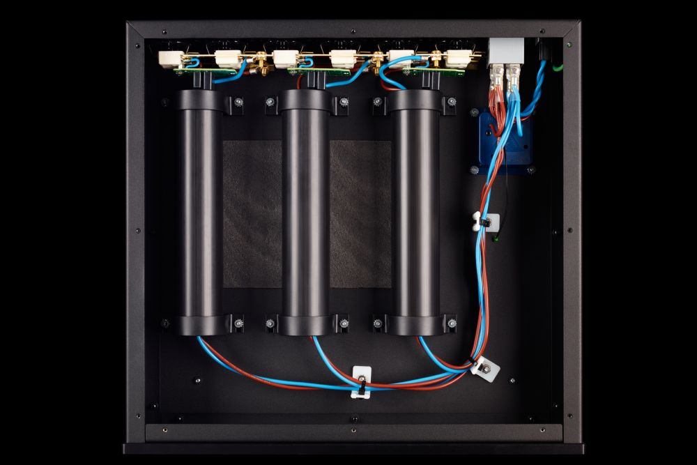
In fact, looking into Shunyata a bit more I think the patent refers to this - the thick tubes pictured:

shunyata-hydradpc6v3-inside-99214-L.jpg


The mains cables simply seem to rely on thick conductors and, to that end and to maintain flexibility, they use multiple bundles of wires. Looking at other cables they have produced they have commonly used multiple bundles woven together with just one ground wire. So I suspect the five wire consist of two for live and neutral and one for ground- this would be consistent with other cables they have made. The tubes above could easily house the metal plates described in the patent and they could be filled with some semi conductive material that would form the resistor. What do you think?
 
The 'swiss-roll-a-tron' is in some ways a flat plate rolled into a cylindirical object. Extend that so the length is much bigger than the diameter and you can regard is a 'wire' with an unusual cross-section.
 
In fact, looking into Shunyata a bit more I think the patent refers to this - the thick tubes pictured:

shunyata-hydradpc6v3-inside-99214-L.jpg


The mains cables simply seem to rely on thick conductors and, to that end and to maintain flexibility, they use multiple bundles of wires. Looking at other cables they have produced they have commonly used multiple bundles woven together with just one ground wire. So I suspect the five wire consist of two for live and neutral and one for ground- this would be consistent with other cables they have made. The tubes above could easily house the metal plates described in the patent and they could be filled with some semi conductive material that would form the resistor. What do you think?
Yes - that rather looks more likely. Possibly I was "searching in the wrong place" for examples of how the patent might be implemented. Looking again at the patent it does seem to insist on conductive strips.


advertisement


Back
Top