advertisement


Turntable speed analysis part II

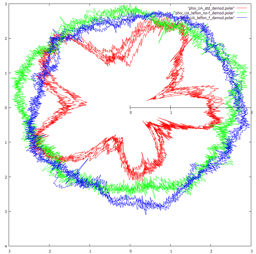
Here the change is not so big indeed. The 2.72Hz is there as this is probably idler surface/eccentricity. Teflon washer seemingly increased the errors in the 10-20Hz range but the comaprison is not fair as the deck is in two different conditions: with and without the console. The motor 25Hz is very clear...strange as the phases are aligned under load to less than 1VAC.

I don't think the noise between 10-20 has increased. The Teflon washer has dropped the overall noise floor making the peaks more distinct, but they remain at almost exactly the same level, around -36db.
 
There's something not quite right with my stuff, I'm wondering if it is phix's use of 22050Hz sampling and some assumption I've made.

This is the polar collection of DC's calibration files,

DC_Calibrate_polar.png


And on the same basis this is the three phix files,

Phix_polar.png


The spectra of the demodulated signals,

Phix_demod.png


The significant bumps are at 0.55Hz, 1.1Hz, 2.77Hz, 5.55Hz, 8.32Hz, 11.1Hz and obviously 25Hz. The first two are eccentricity related.

Paul


Paul, thank you! OK, you both guys seem to converge. Probably I've messed something up with the recordings, no idea how 22.05kHz rate came in..sorry. I'll retake the samples again.
 
On the motor, I don't know alot about the 930' but it appears to be using a 2 phase motor with a capacitor for phase delay. These motors are essentially unbalanced with the phases 90 degrees out of sync.

Adding a 2 phases sine wave generator with precisely configured phase and adjustable voltage may lower the noise a little. One can be made with an iPod, a stereo amplifier and a pair of transformers.

The alternative would be a 3 phase motor, with it's phases inherently stable at 120 degrees apart. Mark Kelly experimented with these with a Maxon ec motor and demonstrated they had incredibly now noise etc, But concluded a dc motor and his controller was easier and nearly as good.
 
Ed, this is a 3 phase motor as far as I know, with the 3rd phase artificially created by a RC circuit. I'm building a dedicated uC controlled power synthesizer to power it.
Earlier in the thread I tried to deduce the 25Hz peak, thinking it was the fundamental
(post #344...ufff...it's getting hard to navigate over the thread :)), but the appearance of 12.5Hz peak shows my calculations should be divided by two (the motor rpm i guess). I've also found 12.5Hz mentioned in the 930 context in the German analog forum.

I know quite well Mark Kelly's article: I was trying to guess if 930 motor is EC as well (it is powerfull @ ~30W). There has been some controversy here in the 927 thread weather the 930/927 motors are synchronous (as the repurted EMT servicemen claim) or induction (as the inspection of innards and the mode of operation with a slip suggest).
 
As I said I don't know enough about the motor.

By EC I just mean that series of motors, not eddy current, in the Maxon case it means electrically comutated or another way of saying brushless dc. That specific series of motors are seriously good.

I would have to see the motor. My business in the USA before coming back to the uk was an electric motor repair shop.
 
Ok, I can't really see the winding so it could be 2 phase or 3. For 3 phases it would need 2 distinct sets of capacitors to create the second and third phase from the primary, not very common, it's likely it is a 2 phase induction motor.

It looks like it has flats on the rotor. These create distinct poles which causes the motor to run synchronously.

The alternative, and seen on other turntables like this is a 2 phase hysteresis motor where the rotor becomes magnetised in operation thus forming the poles to run synchronously, an example being the motors in some roks made by Ashland.
 
Looked a little more into it. It looks like a 3 phase motor being ran off two phases, not exactly efficient or balanced, it works or course. Quite alot of inverters used to drive 2 phases while using the third as a speed reference, or to know where the rotor was.
 
Ok, I can't really see the winding so it could be 2 phase or 3. For 3 phases it would need 2 distinct sets of capacitors to create the second and third phase from the primary, not very common, it's likely it is a 2 phase induction motor.

Ed, there are 3 windings, star connected (at least in 930):

http://www.audiosharing.com/archive/german_audio/emt/pdf/EMT_930.pdf

(scroll down to the first diagram) I understand this is 3 phase, i.e. the voltages between the windings are shifted 120deg.

It looks like it has flats on the rotor. These create distinct poles which causes the motor to run synchronously.

Aha! That's why Germans keep repeating publicly and privately that the motor is syncronous, despite all the evidence to the contrary (lower nominal speed than the syncro, smooth slow down with increased load, etc)
Ed, how is this type of a motor called? Would be interesting to find more info on it.
 
I suppose it would fall into the category of reluctance motors, Much like a stepper.

For the motor to run in its smoothest manor I would run it 3 phase. But the flats will probably induce some slight cogging.
 
For the motor to run in its smoothest manor I would run it 3 phase. But the flats will probably induce some slight cogging.

Ed, this is interesting what you are saying. Why would it cog more run out of
a real 3 phase rather than through the RC circuit?

There is also one peculiarity in the EMT design, you may not know: the felt break which is used to fine tune the speed. This is a spring leaf which presses a small felt O ring against lower part of the platter (close to the bearing). Apart from the speed tuning, I think this system has some effect on smoothing the cogging--it pre-loads the transmission, it also probably masks the stylus drag.

However, people report positive effects while getting rid of the break and powering the motor from industrial 3 phase inverters (e.g. Siemens Micromaster series). then the fine tuning is of course done by the freq. controll. I hope to be done with my linear power synthesizer and experiment with the amount of pre-loading, offset to the correct speed the the frequency.
 
Loading any AC motors collapses the magnetic field a little and reduces cogging, some decks do it with felt pads or eddy current brakes, some do it with tight bearing tolerance and/or viscous drag.
 
sq, so cogging is a monotone function of the field?
the VPI SDS controller lowers the voltage after the motor
has reached it's cruise speed to reduce vibrations, as they claim.

what i'd be very interested to check (hence i try to learn Ed's software)
is an interplay between the amout of breaking (=pre load) , lowered motor volatge
and speed stability. in 930 as i was informed by one of the experts, the speed
variation due to the break is quite small: below 1% IIRC, so motor heating due to increased load and supply freq. hopefully will not be a problem.
 
Ed, this is interesting what you are saying. Why would it cog more run out of
a real 3 phase rather than through the RC circuit?

There is also one peculiarity in the EMT design, you may not know: the felt break which is used to fine tune the speed. This is a spring leaf which presses a small felt O ring against lower part of the platter (close to the bearing). Apart from the speed tuning, I think this system has some effect on smoothing the cogging--it pre-loads the transmission, it also probably masks the stylus drag.

However, people report positive effects while getting rid of the break and powering the motor from industrial 3 phase inverters (e.g. Siemens Micromaster series). then the fine tuning is of course done by the freq. controll. I hope to be done with my linear power synthesizer and experiment with the amount of pre-loading, offset to the correct speed the the frequency.

Because the RC circuit is only running 2 phases of the 3, it is inherently unbalanced. This will induce more vibration, and perhaps cogging than an otherwise balanced 3 phase system would provide.

Id read about the brake, I am not sure what I think about that. Stylus drag doesn't really concern me. On a deck like the EMT, start up speed and reliability is a concern, so you have a heavy duty high torque motor. The larger the motor the more vibration, noise or cogging effects so a pre load to help reduce some of that makes sense.

I would probably rather see the motor ran at a lower voltage, with less torque and perhaps slower start up, at the correct speed with the load of the platter etc providing the pre load for that amount of torque, I cant see drag being an issue, but you could always try a non contact brake like an eddy brake in some way, or thick bearing grease.

I will look at the industrial drives they use, to me at first, this sounds horrific. Most of those run PWM right smack in the audio band, you might get lower rumble, but id worry about everything else.
 
The siemens micromaster runs at 16khz, Id really want that no where near my audio chain. Others run as low as 4khz.
 
Ed, that's why I've designed my own inverter: uC-controled 3 phase sine synthesizer (12bit 3 channel DAC IIRC) + filters + 3x linear amp (3x LM4780, each in the parallel mode) + 3 phase stepup transformer. The uC synthesizes 3 sines 120deg rotated with 12bit (IIRC) resolution. The frequency is controlled with 0.01Hz step. Most is done, incl. the uC module. The synthesized sine looks already really good with a moderate filtering (I have to check it with a spectr. analyzer for HF trash though), THD is roughly 0.1%. It already has a slow startup (2s from zero to max volts).
I hope to have it up and running soon and start testing. If lower volts proves good, I'll implement SDS type of time profile: slow startup to max volts, few secs to reach teh speed, slow turn down the volts to some stable minimum (EMT master told me 90V is the locking voltage).

BTW Stylus drag does seem to be an issue: there is a thread on audiogone mentioning that with seemingly serious people claiming they've seen it's effects on the scope.
 
For drag I meant of audible concern to me vs noise generated by a felt brake, as all things it's a trade off. I don't mean to come across a factual in my musings, it's just opinion or how I'd guide my Choices in function.

The controller sounds perfect, I planned to try something similar eventually, dds chips, ardunio, never got round to it, unlikely I will any time soon.
 
Trying to understand why my last standard file (post #360) was so ugly I retook it with [email protected]:

http://www.mediafire.com/?jnluseyhno4c4ca

deck in the console, different cartridge: FR7f (instead of TSD15SPH), no teflon, fiber washer on the original side

If you guys (Ed, Paul) don't mind to analyze it, I'll proceed step by step, first sorting the standard, then adding one teflon washer (bottom) and another one (top).
The latter makes sense as, contrary to what I thought, the idler goes up if the locking washer is removed. Good! Easier to deal with it.
 
Playing it via computer speakers and measuring with the Android Platterspeed the results seem much better than before, suggesting that the console matters for WF!


advertisement


Back
Top