advertisement


Death and Life of a Nait3

That Acoustica schematic has a number of inaccuracies that have been commented on here before. Add to this the fact that some component values, particularly resistors, were selected on final test in an attempt to keep the amp stable and you have a can of worms! Unless you have sophisticated test equipment it's best to stick with the values that Naim fitted. I've seen early amps like the NAP160 with differences in resistor values between the two amplifier boards. The schematic for the NAP90 is quite different to that for the NAP250.
 
I didn't know that schematic was inaccurate. I assume just component numbers as it seems to match others. Yes of course their a slight component changes between say a 140 and 250 board , a 47uf changing to 68 uf cap comes to mind.

Wow, that's a bit mental - having differing values across amplifier models is understandable, size/style of PSU etc, but across channels in one amplifier seems extreme.

Presumably there is a base BOM and so if you have an amp with a differing value on one channel it means something was required to be tweaked. Unless they were all made like that and it was the layout / distance that required the tweak to one channel. I see also a different shoebox layout to mine on 'net and of course this flat 90 is different too. It must have caused some bother in house!
 
I didn't know that schematic was inaccurate. I assume just component numbers as it seems to match others. Yes of course their a slight component changes between say a 140 and 250 board , a 47uf changing to 68 uf cap comes to mind.

Yes, the feedback capacitor can be 47, 68 or 100 uF. They had problems finding good 100 uF beads and sometimes stuck two 47 uFs in the one pair of holes.

I've done this in detail before on here but, in summary and using the component labels from the circuit linked to above:

  • the polystyrene capacitor on the base of TR1 is normally 470 pF, not 330 pF as shown
  • the resistor on the emitter was originally 'select on test' (sot) and has an effect on the DC offset, originally values between 470R and 750R were used, then they standardised on 560R and later still on 620R
  • The trimmer, VR1, is normally 1k with a 2k2 across it rather than a 2k2 trimmer with a 1k2 resistor
  • two of the resistors in the lower half of SOA circuit are different to compensate for the different topology of the positive and negative halves of the output stage - R8 is 43R not 47R and R10 is 120R not 100R
  • R15 is often fitted as 12R not 8R2
  • the resistor between the collector of TR4 and the base of TR5 is shown in various schematics as 2k0 or 2k7 but, in practice 1k8 was normally used
  • the critical areas for controlling instability are the networks in the bases of TR9 and TR10 the upper one is shown as 560R//(680R + 470pF) and the lower one as 680R//(390R + 470pF) but you find all kinds of values fitted in practice
  • TR5 is shown as a ZTX108 but I've seen ZTX384 used here

HTH
 
Malcom, thanks for that summary - I'll put an revision to that diagram higher up the acoustica 'to do' list. Probably better as a standalone page warning of variance in builds with your notes, if I may adopt (and credit) them.
 
Malcom, thanks for that summary - I'll put an revision to that diagram higher up the acoustica 'to do' list. Probably better as a standalone page warning of variance in builds with your notes, if I may adopt (and credit) them.

No problem but it may be worth asking Mark (MJS) for his opinion - he has far more experience than me in this area.
 
Not sure, where to post it; I had opened a parallel thread asking about servicing a NAP140; while doing this, I noticed a few differences in comparison to acoustica.org.uk's power amp schematic. So I ended up decoding (and measuring) the values of most components on the boards. Attached an image of an early NAP140 board (NAPA5/7), which obviously was fettled with after assembly (1.8K was changed to 1.5K with the board installed). If a generic schematic exists, with a sort of naming standard (C1, R1, etc.), I will happily add these, too.

Best,
Oliver

NAPA_5_7.jpg
 
Lots of work there Oliver, useful information. Take a good hour or two to build a schematic from that, reverse shot would help.
 
As suspected my arrangement to power the pre-section with a 2nd trafo is at fault.

Disconnecting the 2nd trafo and using a DIY SuperRegged HiCap for the pre-amp section via the external sockets, all problems with tripping disappear. Sounds sweet too :D

A single box solution is of course possible and in this case desired, besides I need the HiCAP back on my headphone amp.

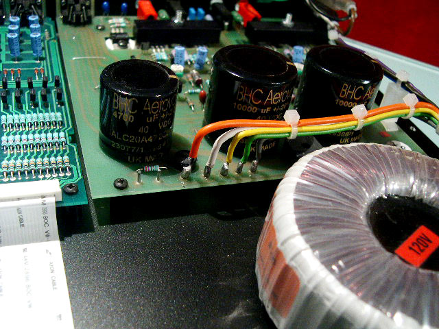
This image of a Nait 3R shows 7 pins.

nait3r6.jpg


In my case, from right to left:

Pins 1-3 - secondaries and centretap from the CD3 trafo
Pins 4 & 5 - secondaries from 2nd trafo

The issue is with pins 6 & 7. On a non-remote Nait3 these link via a 270R resistor to the logo illumination panel.

A diagram always helps.

Nait3R-pre-amp_power.png


Two differences for me: with the remote control version the pre-amp section powers the front panel and on the NAP board I have the 270R resistor is a wire-link.

Pin 6 - is connected to 0V
Pin 7 - is connected (via wire link) to neg leg of the second bridge rectifier

My 'faulty' setup involved bridging pins 6 & 7 to provide a direct return for the second trafo to 0V. Without this link there's no return and no output from the pre-amp supply section.

Question is why does this result in trips and why does the arrangement in the photo above work without a return for the bridge rectifier?

Perhaps if I replace the wirelink going into pin 7 with a resistor (270R + approx load of a logo display) and retain the pin 6 & 7 link it'll work but I'd rather understand things first.

Nick
 
I think I now have an explanation for you.

As I explained previously the NAP90 transformer has one continuous secondary winding. The inner section of this is 22 - 0 - 22 v AC and the wires are coloured grey/green/yellow which are connected to a normal bridge rectifier circuit followed by the reservoir capacitors. This you have replicated perfectly with your first transformer.

The outer section is 27 - 0 - 27v AC and the wires are coloured white/green/orange (that's the same green as for the inner section). This is connected to the smaller bridge rectifier with the positive output powering the LM317 and the negative output powering the logo display (in a NAP90). The operation of this circuit requires a centre-tapped transformer and the one you are using has no centre-tap. (I will agree that this is not shown correctly on the schematic that I sent you).

The NAP90 secondary is one continuous piece of wire - orange/grey/green/yellow/white

I can't see from your photo but would guess that there is a pcb track connecting pin 2 to pin 6 and it is this that establishes the earth return for the smaller bridge rectifier bearing in mind the construction of the NAP90 transformer.

When you link pins 6 & 7 you are connecting the already established earth point to the negative terminal of the smaller bridge rectifier through the 270R resistor - this is not the same as having a centre-tap on the transformer which is what is required.

You only have to google for images of the NAIT3 or NAP90/3 to realise that these power amplifier boards are prone to catastrophic failure. As a result there must be many NAP90 transformers out there doing nothing. I recently acquired two dead NAIT3s and converted them into NAC92s but I'm afraid that I've already sold the transformers. Getting hold of a NAP90 transformer would be the easiest way to complete your project. I may need to think about this a bit more but it may be possible to replace your second transformer with one having a centre-tap. The centre-tap would go to pin 2 and the ends to pins 4 and 5.
 
Thanks Malcolm, that's very helpful, as you say, the transformer schematic does not show a centre-tap for the pre-section; indeed it shows two separate secondaries on the Nait transformer.

You are correct, Pins 2 and 6 are connected via a pcb track.

Hoping it should be possible to finish the project without waiting for a Nait3 transformer since the 2nd transformer I am using has two 25 - 0 secondary windings.

I'd form a 25 - 0 -25 centretap, take the OV to pin 2, and the 25V's to Pins 4 & 5.

Leave pins 6 & 7 unconnected.

Still unclear about whether phase differences between the two trafos would be a problem, after all just tying the centretaps together doesn't make them the same tap!

Cheers
 
Not sure, where to post it; I had opened a parallel thread asking about servicing a NAP140; while doing this, I noticed a few differences in comparison to acoustica.org.uk's power amp schematic. So I ended up decoding (and measuring) the values of most components on the boards. Attached an image of an early NAP140 board (NAPA5/7), which obviously was fettled with after assembly (1.8K was changed to 1.5K with the board installed). If a generic schematic exists, with a sort of naming standard (C1, R1, etc.), I will happily add these, too.

Best,
Oliver

NAPA_5_7.jpg

This is very helpful Oliver and probably deserves a thread of its own. I have, however, noticed a couple of problems:

The resistor immediately to the right of the trimmer is 27R not 27K; 27R is the value on the schematic and the red/violet/black bands in the photo seem to bear this out

You have the two resistors in the upper compensation network as 33R and 27R whereas the schematic has 560R and 680R. As I said, I've seen all kinds of values in these positions but nothing lower than 150R nor higher than 1K, although the bands seem to bear out your values. 330R and 270R would be more believable, have you lifted these resistors to measure them?

BTW the accepted practice is to write 2K7 not 2.7K and 8R2 not 8.2R.
 
Still unclear about whether phase differences between the two trafos would be a problem, after all just tying the centretaps together doesn't make them the same tap!

Cheers

I'd only worry about phase if I were connecting two similar transformers, or two similar secondaries on the same transformer, in parallel.

Your suggestion of turning the second transformer into one with a centre-tap seems sound.
 
Second transformer now arranged as centre tap connected to the centre tap of the primary transformer - all at OV.

No bangs or smoke and music plays :)

But, the rail is still sagging and tripping the mute relay.

Measuring the output from the smoothing cap into the LT1086CT reg (which is set for 24.8V).

@ zero volume - 35V
@ 1/8 volume - 30V
@ 1/4 volume - 25V

a touch farther ... and trip!

So, dodgy smoothing cap? LT1086? 30VA trafo too small? wrong colour underwear?

I'll pop a big Kendeil in for the smoothing cap - it can't stay as its too large for the lid to shut but it'll rule one thing out.

Nick
 
Ah, datasheet for the LT1086 states max input voltage is 30V peak, 25V operational.

Better find an LM317.
 
Hey misterc6,

thank you for checking the image; the error was well-spotted, cheers! I have corrected the image and added the capacitance label of the left-hand cap.

I have just measured two of each of the resistors (27R and 33R, both lifted); all four are +-0.3R in their specified range and are, for all I can see, not labelled wrongly.

Regarding my strange notation - please consider it a hybrid, half Vishay-Dale, half German. I promise to fix this as well as soon as I find the time.

Thanks again & best regards,
Oliver
 
Well this is odd.

Replaced everything (except the rectifier which was new last week).

- tested it with an LT1086, an LM317MT and even an ALWSuperReg.

- replaced reservoir cap with brand new Kendiel 6800uF.

- replaced transformer with a Nuvotem 300VA jobbie which is bigger than the CD3 transformer on power amp section duty.

... and the rails still drop and trip the mute relay.

Ok I can now go a bit louder, '11 o'clock' on the dial, but it can't be size - this psu is bigger than the off-board one which works great!

Off for a glass of something cold to mull it over ...

Nick
 
Ah, datasheet for the LT1086 states max input voltage is 30V peak, 25V operational.

Better find an LM317.

That is the maximum voltage drop across the regulator not the highest voltage.

I have used LT1086s in 36V rails.

Pete
 
An aside, but +1 to that.

Belt-and-braces with any 3-pin reg is to limit the voltage appearing across it at start-up, e.g with a large (1.3W min) zener reverse-biased from Vin to Vout, and chosen for a value rather less than the max differential voltage. On startup, it avalanches and saves the reg, and drops out of circuit once the reg is running (providing Vin - Vout remains acceptable!) Something like a 22v zener works most times you'll want such protection. I've run 317s up well past 300Vdc like this! (but excess input voltage and oversize reg output capacitance should be avoided, obviously)


advertisement


Back
Top