advertisement


Death and Life of a Nait3

Ooh yes, classic.

q1int%5b2103%5d.jpg
 
hmmm,

This reminds me of a problem we had in an industrial application. As more current was applied the 0V essentially was no longer 0V but something like floating above, hence less differential. The solution was lower return impedance - it was BIG wire in that case.

Have a look and see if something could be causing such a thing Nick?

Perhaps you can measure the 0Vs in relation to ground and see if something is moving.
 
Thanks for the thought however it's probably simpler than that.

The current limiter is creating the rail dip. I've been retaining the light bulb tester in place since the last time I ran the amp without it a channel burnt out.

The channel overheat is actually the root issue that needs sorting.

Both channels cook the output stage. The 100R resistors, output tyrannies and emitter drivers all get hot with the wick at 10 o'clock.

After 30secs the PNP emitter driver is the hottest and smokes first.

[edit - another smoke test had the 100R on the positive side go first]

My line is to replace the signal path and feedback caps first and then feed new silicon in for the emitter drivers.

Any other lines of enquiry recommended?

Nick
 
perhaps the amp is unstable due to the speaker and cable, which are as basic, cheap and short as you can get.

I've wound a pair of coils. 16 turns of enamelled wire around a 6mm screwdriver and heatshrinked to about 15mm length.

Question is shall I insert this in parallel with the 0R22resistor on the output or in series?

Les' comment in an old thread suggested series.

Nick
 
If there's any chance a nap90 trafo will do the trick, Stamford Audio have just listed on EBay a NAP90 case with a trafo still in. Only £45 or best offer too.
 
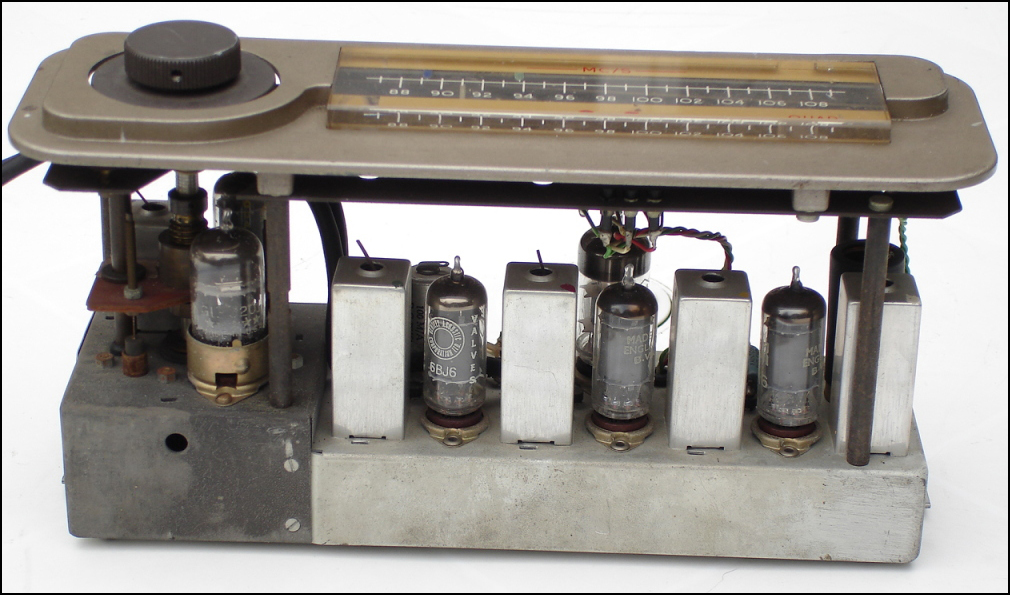
Whilst clearing out the workshop happened across this Nait3 wannabe and decided to have a last pop at bringing it back to the life.

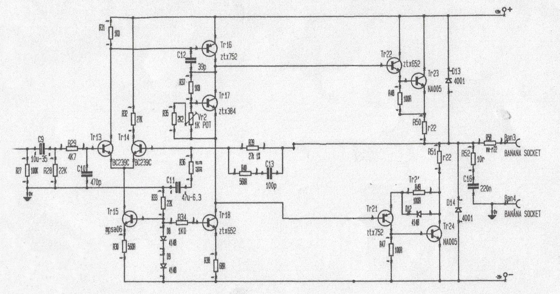
The PowerAmp board (acquired long ago and never tested) is overheating on one channel. It had fried the output trannies on the left channel.

Since then, the trannies and several measurably faulty components (emitter drivers, diodes, burnt resistors) have been replaced along with soa circuitry removal.

I have a current limiter (halogen lightbulb) in series with the mains, the issues are as follows:

1. Power on. No load. No input signal. Temp of output trannies on faulty channel gradually increases to over 100C in 2 minutes. Lightbulb current limiter gradually brightens. Right channel unaffected.

2. Power on. Speaker load on faulty channel. Lightbulb current limiter instantly bright. Right channel with speaker load is no problem.

With the current limiter in place I have about 2 minutes before I need to power-off and cool it down - so I could do with some pointers as to what can kick one channel out like this.

Picking points in the circuit and comparing the good and faulty reveals no differences in measured voltages. Bias is set at 2.9mV both channels. 11mV DC offset at the output on both.

In circuit checking of the transistors and diodes shows no problems (or differences between channels).

Any assistance with tracking down what can cause this?

Cheers
Nick
 
If the output devices are getting hot but you're not measuring any change in bias then were's the current going? - you need to be measuring across both R22s

That's the real Naim CAD circuit BTW. Identical to Nait2 IIRC.
 
Thanks MJ. I'll monitor the voltage across the 0R22 emitter resistors as the output trannies go from cold to hot hot hot.

You're correct, an original naim circuit but 'photoshopped' to remove the soa circuits and clear things up so I can think about what to measure.
 
I would look around tr16-17-18 after blanket change of the drivers and outputs.
You can leave the outputs out for testing.

Pete
 
Thanks Pete,

I'd appreciate some advice about what to measure. I have a scope kicking around.

Those trannies compare exactly with the working channel when using the diode tester on the DVM, voltage drops across c-e, c -b and b -e are the same on all.

Perhaps I should pull them and the neighbouring resistors out of circuit.
 
I would check it unpowered my self.

Resistors around tr 16-17-18 swap them out, check D8-9 their should be a cap across tr17 check/replace that.

I once spent hours looking for a fault that turned out to be a duff transistor that was failing under load, out of circuit it tested fine with an AVO, they only cost peanutsso now they get swapped.


Pete
 
I’d swap parts between working and non-working channel until the problem changed sides...but that’s because I cannot work out weird amp faults :)
 
I would look around tr16-17-18 after blanket change of the drivers and outputs.
You can leave the outputs out for testing.

Pete

That.

Also keep an eye on the voltage across the two diodes D8-D9; and very especially across TR17, the Vbe spreader, collector-emitter. This is where the voltage that drives the standing output stage bias current 'appears'

(Am amazed there isn't a chunky cap across Tr17, but that's a different discussion...)


advertisement


Back
Top