advertisement


Valve amps and loudspeaker impedance curves

ToTo Man

the band not the dog
I’ve been auditioning a pair of Blumenhofer speakers. They are described as ‘valve amp friendly' and present an 8Ω load by means of an ‘impedance linearisation circuit'. This circuit is activated when a two-pronged banana plug is inserted into a special socket on the back of the speaker and deactivated when it is removed.

Details on the impedance linearisation circuit are provided here and here.

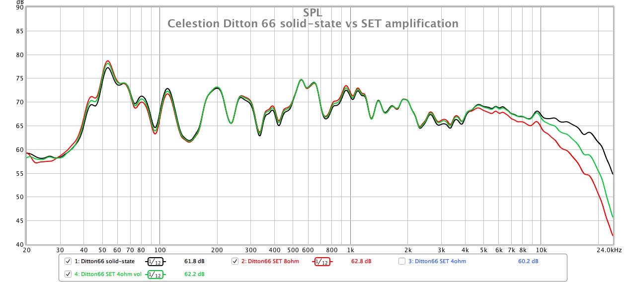
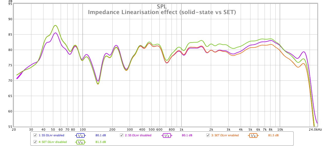
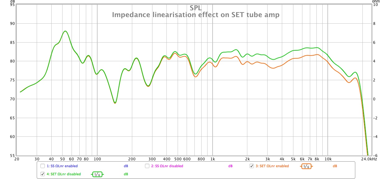
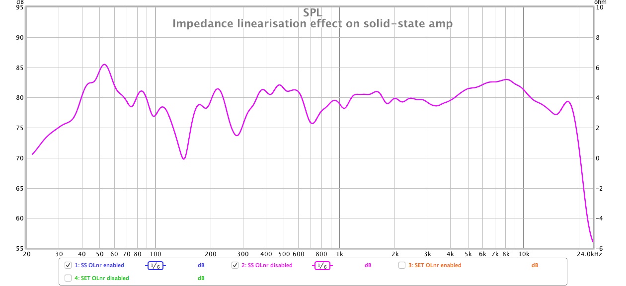
When I drive the speakers with a solid state amp, there is no difference in performance (in frequency response terms at least) whether the impedance linearisation circuit is engaged or not. However, when I drive the speakers with an SET valve amp, the tweeter output level is shelved up by +2dB when the impedance linearisation circuit is NOT engaged.

The information provided in the links above suggest that the linearisation is applied around the LF/HF crossover frequency, but this must be a generalisation that isn’t specific to the speaker model I’m auditioning because the effect I’m seeing is occurring almost across the tweeter’s entire operating range, not just the 1.2kHz crossover frequency.

Based on the above info, is it reasonable to predict that similar FR behaviour will be observed when these speakers are driven by other valve amp designs, or is it more likely that the effect I’m observing is unique to SETs?

I’d also love for someone to explain how the flattening of the speaker's impedance curve is achieved by the speaker's linearisation circuit but I suspect the answer won’t fit on the back of a postcard!

51740474317_207c13a2d6_o.jpg
 
Last edited:
Low or no feedback SET amps typically have a fairly high output impedance on the order of a couple of ohms or more, which will lead to this sort of thing. The high source impedance will interact with the impedance curve of the speaker causing changes in frequency response, though if the speaker's impedance curve is near flat or flatter then this will be less pronounced.

This isn't unique to SETs, any amplifier with a highish output impedance will behave similarly. Amps with feedback are generally far less "needy" with regards to speaker loads as the source impedance becomes far smaller compared to the load impedance.

The impedance correction circuit will just be various parallel components inserted to make the curve flatter.
Thank you for explaining!
 
Low or no feedback SET amps typically have a fairly high output impedance on the order of a couple of ohms or more, which will lead to this sort of thing. The high source impedance will interact with the impedance curve of the speaker causing changes in frequency response, though if the speaker's impedance curve is near flat or flatter then this will be less pronounced.

This isn't unique to SETs, any amplifier with a highish output impedance will behave similarly. Amps with feedback are generally far less "needy" with regards to speaker loads as the source impedance becomes far smaller compared to the load impedance.

The impedance correction circuit will just be various parallel components inserted to make the curve flatter.

Also, I've yet to test whether this amp's bass hump is a result of the interaction between Zout and Zload or if it's part of the amp's tuning, but given that its specs say "8Hz/40kHz –0dB" and the fact that it does not use negative feedback I'm assuming it's the former.
 
Last edited:
Radford Revival is correct. One speaker designer called this impedance linearization a "twister" (don't ask me why). Some sort of LCR is applied to each peak as a separate circuit. So the plug in thing in this case appears to have 2 circuits, one for the upper reflex peak and the other for the crossover region. What I find interesting is the result you found, which is initially counterintuitive. Valve amps apply more power to high impedances so I would have expected the opposite. I'm speculating now that the lower twister (the one applied to the upper reflex peak) enables the amp to comfortably provide a larger power bandwidth, i.e., more bass and treble. Your graph shows more bass and midbass so I suspect that's what's happening here.
 
Radford Revival is correct. One speaker designer called this impedance linearization a "twister" (don't ask me why). Some sort of LCR is applied to each peak as a separate circuit. So the plug in thing in this case appears to have 2 circuits, one for the upper reflex peak and the other for the crossover region. What I find interesting is the result you found, which is initially counterintuitive. Valve amps apply more power to high impedances so I would have expected the opposite. I'm speculating now that the lower twister (the one applied to the upper reflex peak) enables the amp to comfortably provide a larger power bandwidth, i.e., more bass and treble. Your graph shows more bass and midbass so I suspect that's what's happening here.

I may have confused things by posting the results of the solid state amp and valve amp in the one graph. Please see new graphs below.

The impedance linearisation circuit does not appear to have any effect on the woofer's frequency response in this instance, just the tweeter, so the impedance linearisation circuit in the speaker model I'm testing must only be flattening the impedance of the tweeter and leaving the bass driver untouched?

51740952822_611243c288_o.jpg


51742664435_42145a2ab3_o.jpg
 
Could be. The relative levels of the tweeter and woofer (as a big simplification) will b.e a function of the ratio of the impedance of the driver/crossover components and the output impedance of the amp, non-zero for a valve amp. Tweeters generally have a higher impedance as you don't need to sacrifice high impedance for overall voltage sensitivity.
 
I've been out of this game for decades but I still remember the theory.

Valve output stages work differently to semiconductors. First off valves are high impedance devices and the anode load of a class A triode output stage is usually in the K Ohm range whilst semiconductors are in the ohm or lower ranges. Thats why a valve output stage is usually connected to the low impedance speakers via a step down output xformer. This means that the load that the anode 'sees' is directly proportional to the loudspeakers impedance at a particular frequency. If over the frequency range the speakers impedance changes then so does the load of the output valve anode and this changes the gain at that frequency. So the gain of the output stage varies with the impedance of the speaker at a particular frequency.

This doesn't apply to semiconductor output stages.

Fun no?

DV
 
IIRC The theoretical optimum is to choose matching network that is the 'complex conjugate' of the speaker's input impedance. The trade-off is that you end up having power 'lost' in that added network. But can get a flatter response. (Possibly also more stability margin.)

Given high gain and enough feedback you can reduce the output impedance without such tricks. But it means more gain stages. And with valve amps there is then the question of if you put the o/p transformer 'in the loop' or not. That tends to mean an exceptionally good transformer if you also want stability. i.e. cost goes up all round for a given output power, etc.

Radford's talent was in part being able to make excellent output transformers. Unlike Tim D'P he didn't put hardened ball bearinging into the potting to, erm, 'deter' anyone else from taking them apart, though. 8-]

The snag I suspect is that in some cases the user prefers a valve amp *because* of the high output impedance altering the overall response. But it means reviews on the amp 'sound' aren't much help to someone who uses a different speaker to the reviewer. :)
 
Comparing my Celestion Ditton 66 driven by solid-state vs SET amplification has raised a few more questions :):

51846607768_9de8ab4e3b_o.jpg


Significant high frequency roll-off occurs when driven from the SET's 8Ω tap which, AIUI, suggests that the tweeter's impedance drops at higher frequencies?

The high frequency roll-off isn't as strong when driven from the SET's 4Ω tap, is this because the 4Ω tap provides lower output impedance?

When I measured from the 4Ω tap I needed to increase the amp's volume by +2dB to match the 8Ω tap's output level, is this typical?

When valve amp users anecdotally report that their particular speakers perform best on their tube amp's 4Ω, 8Ω, or 16Ω tap, is this due the kind of frequency response variations illustrated above or is more to do with matching the voltage swing and current delivery to their speakers for maximum dynamics and headroom?
 
Comparing my Celestion Ditton 66 driven by solid-state vs SET amplification has raised a few more questions :):

51846607768_9de8ab4e3b_o.jpg


Significant high frequency roll-off occurs when driven from the SET's 8Ω tap. This suggests that the tweeter's impedance drops at higher frequencies, doesn't it?

The high frequency roll-off isn't as strong when driven from the SET's 4Ω tap, is this because the 4Ω tap provides lower output impedance?

When I measured from the 4Ω tap I needed to increase the amp's volume by +2dB to match the 8Ω tap's output level, is this typical?

When valve amp users anecdotally report that their particular speakers perform best on their tube amp's 4Ω, 8Ω, or 16Ω tap, is this due the kind of frequency response variations illustrated above or is more to do with matching the voltage swing and current delivery to their speakers for maximum dynamics and headroom?

Indeed the 4R tap has inherently lower output impedance than the 8R one. Into 4R it also has less sensitivity as you found and will have less power also, theoretically half the power but many things come into it. THD will usually be lowest into the correct impedance for the tap as well.

As to the questions in your last paragraph that's a yes to all of them.
Thanks Jez! :)

The amp in question is 30wpc, it doesn't say if this is into 8Ω or 4Ω but I assume it's the former. If the 30wpc is indeed into 8Ω then generally speaking you'd expect the power into 4Ω to halve to 15wpc?
 
Thanks Jez! :)

The amp in question is 30wpc, it doesn't say if this is into 8Ω or 4Ω but I assume it's the former. If the 30wpc is indeed into 8Ω then generally speaking you'd expect the power into 4Ω to halve to 15wpc?

That's bloody powerful for an SET!! If it has 4, 8 and 16R taps then each should give 30W when used with the correct impedance load. So many things come into it that in practice you could get anything from say 12 to 25W (very ish!) using the 8R tap into 4R.
 
That's bloody powerful for an SET!! If it has 4, 8 and 16R taps then each should give 30W when used with the correct impedance load. So many things come into it that in practice you could get anything from say 12 to 25W (very ish!) using the 8R tap into 4R.
It has 4Ω and 8Ω taps. I understand now what you're saying about obtaining the same power output when used with the correct load, i.e. an 8R on the 8Ω tap and 4R on the 4Ω tap should both get 30W, but will be less in practice if the load's impedance curve isn't purely resistive.

BTW - You're the second person to make comment about the unusually high power output for a SET... The amp in question is a Mastersound Compact 845 integrated. They actually make an integrated that produces 55wpc using four 845 tubes instead of two, - I can only imagine the heat produced by that one as the Compact 845 sure keeps my room toasty!
 
Mastersound 845 Compact
Bildschirmfoto-2022-01-27-um-23-46-50.png
Thanks. :) With a bit of searching I found the original review here.

The review appears to be from an earlier version of this amp, the photos look different to the model I have. Perhaps this explains why the high frequency response is rising in their test? Do you know what testing method they used?
 
You could have a laugh by replicating the high output impedance of the amp by putting suitably rated resistors of say 2.2R or 4R7 (or have fun experimenting!) in line with the speakers when using a SS amp and measuring that...
 
a: The review appears to be from an earlier version of this amp, the photos look different to the model I have.
b: Perhaps this explains why the high frequency response is rising in their test?
c: Do you know what testing method they used?
a: I think the whole circuit is more or less the same with the successor amplifiers.
b: No, it seems to be the output transformers of Mastersound. I have another review of the successor amplifier were this is mentioned too.
c: What do you mean with testing method?
 
I have had this problem with the LS50 Meta. When driven by my valve amp (PP KT88) the midrange is rather prominent.

A quick look at the impedance curve provides the most likely answer. Just look at the impedance change from 500Hz to 2.6 KHz!!:
https://www.stereophile.com/content/kef-ls50-meta-loudspeaker-measurements

The 100Hz peak would also most likely cause audible bagginess if I was using the Metas at LF.

And to think that KEF used to offer conjugate matching networks in the past ;)


advertisement


Back
Top