advertisement


TeddyReg voltage set help please?

Ant

pfm Member
I purchased 2 x populated TeddyRegs from misterc6 set at 37vin/28vout in scope to convert one to 12v and the other to 5v.

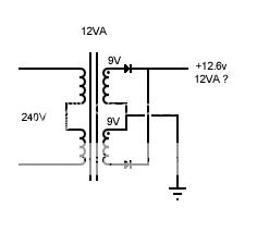
My transformer is 18.5-0-18.5 so after rectification (x1.4?) they're 25.9v secondaries.

I thought it would be easy(ish) but I'm completely stumped, can anyone tell me what values of resisters need to go where?

Thanks,
Ant
 
Hi, you have a task there. Teddy might help you, he was good to me when I bought straight from him. Misterc6 will probably help in any case.

the teddy web site gives lots of instructions for DIy folks.

Make sure you don't have too much current draw.

My 5Volt squeezebox STR has an extra component to cope with the extra current required. The STR works well as did my 2x24volt TR as a hicap clone.

http://www.pinkfishmedia.net/forum/showthread.php?t=39990
 
Just a quick point - depending on how much current you want these to supply you may need to provide some serious heatsinking, because of the large voltage drop.

Example, 100mA at 5v you'll be dropping 20v at 100mA = 2watts, not a problem with a small tab rated 10degC/W or so. But if you want 5v for a squeezebox or similar, at say 750mA you'd be dissipating 15Watts and need a rather large lump of metal - a lower voltage transformer might be more economic! Something to think about, anyway.
 
Hi, you have a task there. Teddy might help you, he was good to me when I bought straight from him. Misterc6 will probably help in any case.

the teddy web site gives lots of instructions for DIy folks.

Make sure you don't have too much current draw.

Thanks mudlark, I'm really stuck with this one.

Current draw - Please see below


Just a quick point - depending on how much current you want these to supply you may need to provide some serious heatsinking, because of the large voltage drop.

Example, 100mA at 5v you'll be dropping 20v at 100mA = 2watts, not a problem with a small tab rated 10degC/W or so. But if you want 5v for a squeezebox or similar, at say 750mA you'd be dissipating 15Watts and need a rather large lump of metal - a lower voltage transformer might be more economic! Something to think about, anyway.

Hi Martin,

The draw on the TR's will be small - around 70-80mA each (if that) so I'm guessing the tabs will cope?

Ta,
Ant
 
Hi Ant,

sorry for not posting sooner but I had a day off yesterday for my birthday.

As I pointed out when you bought the TRs your input voltage is far from an ideal starting point in trying to achieve the rails you want.

The calculator that Neil linked to is very helpful and Teddy pulled all the information about the TR together in this thread, which in itself links to the original thread:

http://www.pinkfishmedia.net/forum/showthread.php?t=39990

Especially with such a large voltage drop you should aim to split it equally between the two two stages. This will also spread the dissipation between the LM317 and the D44H11.

I think I'm correct in saying that R1 and R2 are the opposite way round between Teddy's schematic and the silk screening on the pcb. i.e. R1 on the schematic is R2 on the board and vice versa.

malcolm
 
Just as an aside....would the knowledgeable types think that cascading the devices would provide two good power supplies? I mean produce a 12 volt regulator then connect that to an output and the input for the 5V regulator.
 
I've tried Neil's calculator but it won't allow me to change the values in the green boxes.

Here's a rough calculation for the 12V reg, I'll try and find time to do the 5v later. I've done this in such a way that you change as few resistors as possible.

I've assumed that your 18V transformer gives (18*1.414) ~25.5Vdc
change R1 to 240R and R2 to 3k3, this will give ~18.5Vdc out of the LM317
leave R3 as 120K but change R4 to 220K

Now 18.5*120/(120+220) ~ 6.5 V dropout over the D44H11 and 18.5 - 6.5 = the desired 12V. The dropouts are approximately equal at 7V over the first stage and 6.5V over the second stage.

I would advise checking the actual voltage from your transformer/rectifier/smoothing circuit under a similar load to that which you expect to have. Note that resistor tolerances will affect the figures given,

malcolm
 
... and for the 5V supply:

R1 = 200R
R2 = 2K2

giving ~ 15V

R3 = 120K
R4 = 56K

this gives a dropout of ~10V per stage.

malcolm

p.s. but something in the back of my brain says that R4 should be bigger than R3?
 
The main difficulty is that an 18V transformer is not where you want to be starting in order to get a 5V regulated supply! Given the low current requirement it would surely be worth getting a small transformer with a 7 - 9 V secondary.

malcolm
 
Sorry for the delay in thanking you guys - away for a few days, so thanks :)

I see the main cause for concern is the 18.5-0-18.5 tx which I understand completely in regards to drop-outs and heat dissipation, so.....

I built 4 small PSU's that are currently sat in a cd player that I never use and they look like this:

DSC_0539.jpg


They have twin 9v (12.73v aft) secondaries rated at 211mA per side currently configured in parallel through 4A shottkys - So would they be ok? would 422mA be enough for a single TR and say 80mA draw?

Datasheet (0380909):

http://www.spitznagel-gmbh.de/pdf/trafo_spk038.pdf


Hoping the small transformers will be okay - I've worked out on the spreadsheet (cheers Neil) for 5vout:

R1 = 1k2
R2 = 200r
R3 = 1k
R4 = 2k

That gives a pretty damn equal 3.98v drop-out on the 317 and 3.92 on the gyrator producing 4.83v.... Close enough I think?

For the 2nd TR, I can go with 10vout (as opposed to 12v):

R1 = 1k6
R2 = 200r
R3 = 200r
R4 = 6k

Giving 9.89vout and gyrator 1.36v drop, 317 @ 1.48v actual drop (not enough for the 317?) Can I give the drop-out all to the 317 and none to the gyrator, can it work like that?


Cheers,
Ant
 
Am I asking silly questions? Please enlighten me if so.

Ant, You aren't asking trivial questions hence my original comment.

I have a preamp which required two power supplies. It's beyond my knowledge to build two different voltages off one transformer so guess what I did? Yup I used two transformers. Although this would be crazy in the real world, in my world of DIY more is better (probably not). The benefit is that the transformers can be run at a low voltage as just gets the circuit to work. This means less heat, more efficiency for the price of a separate transformer regulator and capacitor set. I was lucky as the non audio circuit had a regulator and capacitor set on the motherboard.

looking at a Dac that I bought from far away, the transformer has two sets of secondary windings...
 
The problem, as I see it, is that an 18v transformer is not ideal for a 12v psu and totally inappropriate for a 5v psu.

I'm not clear where you intend fitting the supplies but I'd advise getting two small transformers one at 15v and the other at 9v which should give plenty of headroom for the TRs. They only need to be about 5VA each and Farnell sell suitable toroids for around £10 each. A bridge rectifier and single smoothing capacitor for each should suffice.

malcolm
 
mudlark - Thanks for your help, much appreciated.

Malcolm - Many thanks for your time and the guidance, oh and a happy belated birthday too.


Cheers,
Ant
 
Righty then - We're back on....


I've ordered 2 x transformers, one 9v and one 15v. I've been reading through Martins super site (aka acoustica) and decided to go for EI types over toroidal, if they're good enough for the guys who know about this stuff then they're certainly good enough for me.... and they're half the price - bonus :)

So if anyone would be kind enough to help me work out R values for the TR's, that'd be great!

I need 9v > 5v & 15v > 12v

Also can I confirm that the PCB's differ from the spreadsheet in terms of R1/R2 - are they printed the wrong way round on the PCB?

One last thing - Back to basics....

Does this look right? Or is there a better way? Diodes are Hexfred HFA08TB60.

psu.jpg


Thanks,
Ant


advertisement


Back
Top