advertisement


Superregs are rubbish inside my CD3.5 ... why?

That's a good thought and certainly worth a try - it can be hard to get an area of PCB foil hot enough to make a clean junction.
 
Carl,

Whilst I doubt its the issue, the outut and ground wires from each reg should run parallel and next to each other, or be lightly twisted.

The spacing between yours in that photo gives a large loop area, raising potential noise pickup problems.

Nick's wiring is great as an example ;)

Andy.

Edit: Your earlier wiring was fine too - I guess the inductor experiment gave rise to the spacing.
 
Thanks, Andy - you're right: the wiring was only temporary. I've sorted it out now and the problem wasn't the SRs at all, but was twofold: first, I'm jaded, tired and my ears have still got that motorway whooshing sound in them from a long drive today; secondly, I think I introduced a problem during the move of the SRs from PSU to cd3.5.

I had added a couple of wee lm1086-based preregs in the PSU to deliver 24.4v into the player, where the SRs stepped that down to 18.3v. The 15-year old 15000uf felsic caps in there are pretty shagged, and combined with 220uf jamicon cheapos on the 1086 outputs, seemed to be f**king up the sound.

I replaced the 220uf cheapos with 1000uf panasonic NHGs and (just for good measure) supplimented the felsics with another couple of NHGs right at the input pin on the 1086s.

My ears are still jaded, but I can tell that the combination of moving the SR 0v connections to the pin, replacing the crap caps and adding the 1R//inductor has improved things. Being tired, I think I'm going to listen to some Zero 7 at low volume for a while...

Edit: Andy, is the silmic/tant on c3/c5 likely to be improved upon by use of a 22u starget?

Cheers,
Carl
 
Oh dear I seem to be having similar woes..

Andy maybe if you read this you can help me out too. I seem to be in a state of one step forward two steps back...

Just done two mods at once and seemed to have b*ggered up the sound.

The mods I did were:
Add 220uF rubycon ZLs and Oscon 10uF to my superclock 2 (as per your details in best clock upgrade thread), AND change C3 to 22uF starget and add C5 to 22uF starget and change C2 to Oscon on my SRs ( damn I knew I should have done 1 thing at a time - a lesson to be learned here).

The problem is the sound has lost a LOT of soundstage, and the bass whilst definitely present has lost extension, basically very shut-in sounding. SR's still seem to be giving 18V o/p OK.

I guess I should either undo one of the mods, or quickly put LM317s back in place of SR's just to get a baseline. To be honest from the sound I'm guessing I've just ended up with a very jittery clock for some reason.

Any advice would be welcome before I go about retracing my steps. Roll on the weekend...

Thanks,
Stu.
 
Stu, sorry to hear you've got similar cdp woes :(

On the other hand, it'll be good to get your pink flea into action in there :)

I've discussed the problem with my friend, Mary-Jane, and we're both in complete agreement about one thing: the stereo is sounding mighty fine right about now :D Of course, she's a bit biased, but a bit of John Lee Hooker and some Black Rebel Motorcycle Club have certainly make a good case for the problem being solved.

Hope you get some similar luck,

Edit: I've just noticed you've got 22uf stargets in c3 and c5. Have you tried removing the one from c5 to see if it makes a difference? I think C5 is normally left out initially.

Cheers,
Carl
 
Thanks Carl,

Just did as you suggest and removed C5 from both regs - Problem fixed!!

Wow - I amazed this made so much difference - night and day really. I only added C5 as I read somewhere that it might calm down the potential shrillness of the superregs - put them to sleep more like in my application.

Mind you not convinced yet that this new "working" state is any better than where I was before, time for some more listening me thinks...

It's got me wondering what is going on here though, as I am surprised it is this sensitive - OPA627 Op amps in CDP BTW. C3 and C5 are effectively in parallel albeit starred to different points. I'm sure Andy said that less C= "better" sound. So bearing in mind C5 was awful what about C3 = 10uF? I have some nice 10uF silmics I could use :). I would like to try and get a grip on the theory of this first though before just sucking and seeing...

Andy please?
 
Very fast opamps and very fast active PSU = lots of potential for ringing, if not outright oscillation. Add-in a touch of inductance (loop area in your wiring ) and low-ESR caps and bingo, what was marginal case is sufficient to cause audible annoyance - even when the ringing is far above 'what you can hear' (!)

Caps with some ESR (like silmics or tants, or even adding 0.5R in series) can actually a good thing - it's free damping! I've been doing some poking about on just this lately & hope to put a short page together soon.
 
Hi martin,

Thanks for that, I look forward with interest to you posting your findings.

Well after a bit more listening I still felt the sound was a little bit behind it's original position (i.e removing C5 was about a 70% fix), so I decided to return the S-R's to their original state one step at a time.

Swapped C3 back from starget to Rubycon ZA - definite further improvement - more dynamic, less "constipated" sounding, better PRat. (still a bit confused because I thought ZA was Lower ESR than starget??)

Then C2 from Oscon back to ZA - better still - more texture, detail, ambience. Not sure I can explain this one - do Oscons require some burn in?

Anyway now I do feel I'm back at 100% - will await your update before trying any more tweaking on the S-Rs
Thanks,
Stu.
 
Don't hold yer breath Stu...

Looking at this again, C3 and C5 are effectively in parallel so changing one probably affects the effect of the other - and we already know that parallel caps can be a bit of a crapshoot in terms of effect. So maybe removing one half of the combo, and ending up with one cap of low ESR is just what the circuit really wanted in your implementation.

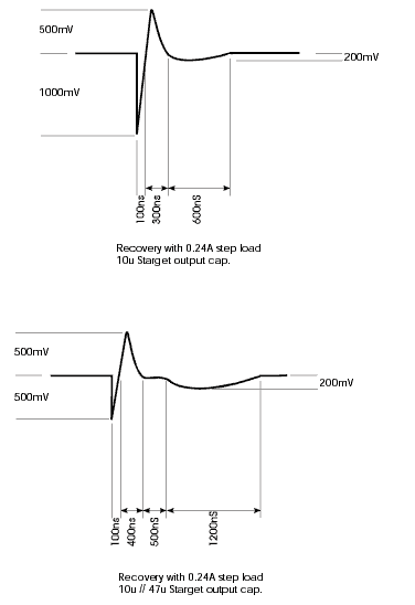
Andy did some measurements* (quite some time ago) on the effect of using either a 10uF Starget, or a 10uF in parallel with another 47uF at a reg's output. Looking at the effect of a step-change in load on the reg with the paired caps, the initial transient in output voltage was halved, but the effect had a *much* longer settling 'tail', you could quite clearly see two superimposed 'recoveries' in the trace. The 10uF cap alone resulted in a greater transient dip in voltage, but cleaner and rather faster settling. I'd bet the effect is audible.

Not sure I can explain this one - do Oscons require some burn in?
Dunno, but IMO they do require a few hours to settle after being soldered; when I've used them I've often felt 'the good stuff' only finally arrives after running overnight. Not entirely sure why this should be - maybe the leakage current drops after the first few hours powered up..?

*Edit: found it, taken from correspondance with ALW:
regcaps.gif
 
Interesting. I can see me snipping the legs of those tants tomorrow... That'll leave just 10u silmics in c5.
 
Martin,
Very interesting and really got me thinking now - dangerous I know :)

First thought is that one S-R powers the output pair of op-amps the second powers the previous four op-amps.... therefore the optimum value of C5 will presumably be different for each S-R (e.g. if 22uF is optimum for the one powering four then 10uF might be optimum for the one powering two ?).

Secondly from memory I'm pretty sure there are some 10uF tants on the board which were across the outputs of the original 317's - I'm wondering how much influence these are having - is it even worth trying removing them?

Thirdly, it's got me wondering about grounding again. I'm using local sensing with each S-R connected to it's respective gnd point near to original 317's as per Naim's layout. Some of you seem to be starring the gnds to the gnd plane near the output op-amp pair. Now, I'm wondering wouldn't the optimum arrangement be separate runs to the gnd plane close to the respective op-amps that each S-R is powering?

Lastly it has always nagged me as to why the bare Cd5 and CD3.5 seem to be voiced so differently when they use ostensibly the same components but on a different PCB layout. From a the photos I have seen it woud seem the biggest difference in layout are around the output stage and placement of the 317s.....

Stu.


advertisement


Back
Top