advertisement


Superregs are rubbish inside my CD3.5 ... why?

Hi Nick,
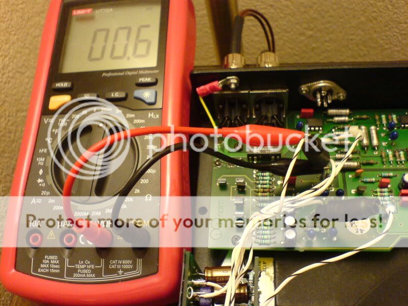
Stupid question - have you tested the preregulator in your SR like described by Andy on page 9 in his SR Manual ?
If you have R2=1K and R3=1K, than it is possible that prereg is not working properly. I had this problem and Andy adviced me to change both R2 and R3 values to 499R, than the prereg was working properly.

Some photos of my work, maybe it will help you.

assembled SR

http://photobucket.com/albums/y252/praganj/?action=view&current=IMG_2309.jpg

Built in SR

http://photobucket.com/albums/y252/praganj/?action=view&current=IMG_2312.jpg

Ready

http://photobucket.com/albums/y252/praganj/?action=view&current=IMG_2322.jpg

Earthing detail

http://photobucket.com/albums/y252/praganj/?action=view&current=IMG_2321.jpg

In my case the SR was improvement. IMHO 3.5 with two SR is better than normal 3.5+hicap.

Cheers, Tomek
 
Hi Tomek

Thanks for your pictures - its always good to review anothers work, besides a picture certainly can replace 1000 words.

I notice a couple of things in your implementation:

1. You are not using remote sensing for either O/P or 0V
2. You use seperate 0V connections for each reg
3. You use a heavier gauge of hook up wire
4. You use Oscon's and Silmics
5. I like the copper plate! :)
6. Insulating 'snot' looks a lot less fiddly than silpad!

First step will be to get some more hookup wire as I've run out of the good stuff and then follow suit with removing the remote sensing lines.

Cheers

Nick
 
nickcase said:
Hi Tomek

I notice a couple of things in your implementation:

1. You are not using remote sensing for either O/P or 0V
2. You use seperate 0V connections for each reg
3. You use a heavier gauge of hook up wire
4. You use Oscon's and Silmics
5. I like the copper plate! :)
6. Insulating 'snot' looks a lot less fiddly than silpad!

Hi Nick,

1. I asked few masters here how to connect, and they adviced it this way.
I have no idea about electronics, i can only build something according to some detailed instructions.

2. I am using earthing close to the original LM317

3. This way i can get a lowest impedance, seems to be very important. It is just a good quality copper wire.

http://photobucket.com/albums/y252/praganj/?action=view&current=IMG_2313.jpg

4. There is only one Silmic (first from the left) and one oscon - second from the left. ALL other components are exactly the same Farnell numbers as from Andys list.

http://photobucket.com/albums/y252/praganj/?action=view&current=IMG_2047.jpg

5. This is just one piece of double side copper pcb, this way all four regs will have similar temperature and both sr will have similar work condition, so there will be less difference between right and lft channel.

http://photobucket.com/albums/y252/praganj/?action=view&current=IMG_2311.jpg

6. This is not silpad, it is a kind of special transparent plastic foil for insulation and some silicon grease.

;)
Cheers, Tomek
 
Well, I've just finished popping SRs into my cd3.5... time will tell if they're any good, but initial impressions are positive. Unfortunately, GAF is low tonight due to Cold Mountain showing on TV :rolleyes: ...

Anyway, some obligatory pr0n:

The initial external analog PSU that I was using (LesW twin-centre-tapped 25-0-25 trafo, 4x MSR1560 schottky rectifier diodes, 2x 15000uF felsic safco caps from a hicap, SRs @ 25v):

dsc00364.jpg


I stripped the SRs out of it and built the following circuits to act as a prereg. They're standard lm1086-based regs set to output 24.4v:

dsc00362.jpg

dsc00365.jpg


Next up came the process of popping the SRs into the cd3.5, which meant first removing the lm317 regs by snipping their legs, removing the leftover solder and crap, cleaning up the holes and inserting new pins:

dsc00368.jpg


I scraped an area off the analog 0v ground plane (see the area to the right of the two blue tants at the top of the picture):

dsc00369.jpg


The 2 SRs were then reconfigured to output 18.4v (R8=1k3, R9=800R). This gives exactly 6v headroom from the 24.4v raw/pre-regged supply:

dsc00366.jpg


Finally, it was all hooked up with some of Les' ptfe wire:

dsc00371.jpg


I'll get some QT with it fairly soon, I'll share my impressions here. Some things to note:

1. I used local sensing on the SRs
2. I used star 0v grounding, instead of seperate 0v returns for left and right
3. The SR C3 is a 10uf/35v tant; C5 is a 10uf/50v silmic 2 (it's what I had, I should replace 'em with a 22u starget or ZA)
4. Cout on the lm1086 circuit is a cheapo 220uf/25v Jamicon electrolytic. Perhaps I'll replace it with something 'better' - any suggestions?
5. Cadj on 1086 is a 10uf/35v tant

Cheers,
Carl
 
Hi Carl,

Nice work, it's always good to see someone else's handiwork. It's got me thinking that I should look into some of that PTFE hook-up wire when I re-tweak my S-Rs.
My 22u stargets just turned up today - what parallel lives we lead.

You should also find an e-mail from me, I'm in the market for a PFM clock...
 
Carl,

You put me to shame again, I've still not found the time to re-try local SR's.

My first thought looking at your pictures was "what is that tant doing on your SR's?". I cannot begin to work out what the effect of it will be.

The wife is out tonight and I'm babysitting, so it finally looks like I'm going to get some build time in tonight - woo hoo!! :)

Nick

Hopefully we can both report positively.
 
nickcase said:
My first thought looking at your pictures was "what is that tant doing on your SR's?".

I just wanted to get the capacitance up to around 20u :D It's not a permanent feature, I can assure you! I'll get some stargets on there I reckon.

When we getting together for a session, then?

Cheers
Carl
 
Didn't take long. Remote sense is still in place on the 0V lines but changing to local sense on the output has sorted things out.

The difference to the previous superreg implementation is night & day. Whereas now I can hear an immediate change compared to the LM317T's.

Only 3 tracks into Pat Barber but timing seems better. There is a lot more control and less effort to her voice, the spaces are darker and generally all seems as it should do when analog devices have better power :)

Anyway - more views later - in the meantime some p0rn.


CloseofSRregconnection.jpg


CD3.jpg
 
Hehe Nick said a rude word, its supposed to be pr0n :D

Now we know what you do when your not listening to Pat Barber!

... yes soldering and making a good job of it too ;) nice pics
 
tsk tsk - we are all adults here

- everyone knows what your left arm is really for!

... holding the solder of course :)
 
Try XRCD or MFSL edition of Pat B !
Also available on p2p ...

Tomek - had to do some googling and wiki'ing to work out what the hell that meant :confused:

I've never tried these extended/enhanced CD's - some interesting technical topics too, hmm - I take it you like the sound then?

Nick
 
nickcase said:
I've never tried these extended/enhanced CD's - some interesting technical topics too, hmm - I take it you like the sound then?

Nick

I have some good copies of XRCD and MFSL and in most cases (not always) they sound better than a standard cd.

Tomek
 
Ok, so the superregs are terrible in the cd3.5. Harsh, shrill and not a lot of fun... makes me wanna turn it down!

Before I go back to the drawing board, is it likely that the 10u silmic/10u tant combination in c3/c5 are causing this? Everything else is pretty standard (as you can see from the pictures).

Any clues? Nick, I know how you feel now!

Edit: first thing to try is inductor // 1R as used in my preamp. Anything else?

Cheers,
Carl
 
I've made some inductor//1R jobbies and stuck 'em in. Can't say as I'm noticing much difference in sound, but there's something wierd going on. Measuring the voltage drop across the 1R on each channel gives 2mV and 0.6mV respectively! Why? I don't know.

It also raises another point: how much current does an SR need to deliver to become stable? Given that there's only 2mA and .6mA being drawn from the SRs, is that enough for stability?
 
there's something wierd going on. Measuring the voltage drop across the 1R on each channel gives 2mV and 0.6mV respectively! Why? I don't know.
er,, look slike you're measuring teh voltage across the near-short circuit of the inductor across the resistor. Otherthan that, yes teh curent drqaw is different - becasue the split is front/back, not left:right (so one reg supplies the two output LPF opamps, and the other reg does the other four).

I've still no clue why it's not making you happy though..! Wild thought: remove the inductor and try just the 1R in series in each channel, or double-up to 0R5.
 
martin clark said:
yes teh curent drqaw is different - becasue the split is front/back, not left:right (so one reg supplies the two output LPF opamps, and the other reg does the other four).

Aha! That would certainly explain things ;) Bloody amateurs... :D

martin clark said:
I've still no clue why it's not making you happy though..! Wild thought: remove the inductor and try just the 1R in series in each channel, or double-up to 0R5.

Haha, wild indeed. Another thought though... You see where I've got the 0v points from the SRs connected? I'm worried that pushing the wires up against a scraped bit of PCB isn't getting a good enough connection. I'd get a far better connection if I soldered them to the earthing pin that connects 0v to the chassis (the one with the yellow wire in the pictures). Is this a good idea?


advertisement


Back
Top