advertisement


Starfish revival

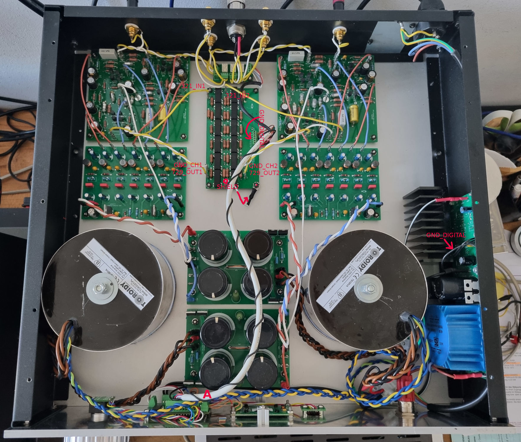
Sorry, I am an amateur diyer and have a lot of wrong imaginations how things work ;-) But I have good ears... I re-routed GND as Martin suggested in #132. Hum/noise got better only very slightly, so I took out the inductors and lowered gain on the preamp boards (2K55 / 10uF WIMA MKS4 in the feedback). Each change did make a small improvement, alltogether it's fine now and sounds cleaner. With high volume settings I still can hear some hum/noise at 1m from speaker without playing music:

hum:
0dB (stepped relay attenuator set to full volume): hum audible
-3dB (stepped relay attenuator set to -3dB): less hum
-6dB: hum almost inaudible
-9dB: hum inaudible

noise:
0dB: noise inaudible
-1dB: noise almost inaudible
-2dB~7dB: noise audible
-8dB: noise almost inaudible
-9dB: noise inaudible

So I wonder if the relay attenuator has too high resistor values? I used this calculator (click on "resistor calculator") and generated values for a 20k pot equivalent:

hTBB1nK.png


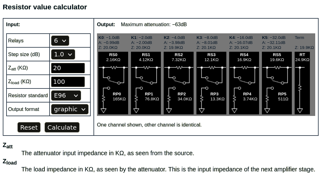
Did I get it right...?
 
Show us please, very exactly, how this attenuator is connected inside your preamp - where does its '0v' end connect for each channel, and how, and how long the wires are... from input jacks to the preamp PCB.

Also - the same for the power delivery to the attenuator PCB, both teh +ve, and the 0v return(s)

= More pictures, please!
 
The yellow wires are signal, white is GND, power to the attenuator board comes from the blue transformer into the green srew terminal on the attenuator PCB together with the serial lines from the microcontroller. The 5V supply line continues from there to the small input selector board with the 3 white relays:

BHtvWuO.jpeg


Analog GND from the attenuator board goes to each preamp board's signal star ground point (left, right and digital circuits are completely separate). The attenuator board has copper layers above and below the digital- and relay tracks to shield them away from the analog signal tracks, only connected to chassis with the screw at the corner of the board (if I disconnect here I get louder clicks: maybe some kind of EMF?). Digital-GND is connected to chassis near the blue transformer. Analog-GND is floating: it is earthed in the source (CD-Player, DAC...), but mains PE in the preamp is connected to chassis as well, so with the buzzer I can confirm signal-GND at the chassis if the source is connected (goes appearently through a long way through the wall socket). The clicks during volume change I can only hear if no music is playing: with music they are too soft to disturb (only the MSB flip makes a click loud enough to be heard through the music). The picture is before I made the changes you suggested in #132: the only difference now is that the 7x regulator boards have onle one white wire coming from the PSU boards which is twisted together with the brown and blue wires and a new GND wire between the 7x regulator boards and the preamp boards. The copper bars you told me to add are fitted under the PCB (I used thick solid copper wire and made a T between the zener diodes: the end of the downstroke of the T has the white wire going to the star GND point of the preamp PCB, and the white wire coming from the PSU connects between the zener diodes). Here is a picture:

UfpagGD.jpeg


BTW if I connect a RK27 blue Alps 20k pot in place of the relay attenuator with the same wires I get the same hum but less noise (the remaining noise is like what I remember from a Naim preamp with volume turned all the way up).

I have the feeling that the noise has to do with the resistor values of my 20k attenuator - would a 10k attenuator make life easier for the preamp stages?
 
Last edited:
Today I reverted back to the original gain setting because I felt some life was lost in the music. I took a picture of the copper bar I fitted as Martin suggested:

c8ni6AH.jpeg


And this is a diagram I made about the earthing that I currently have:

HmXW8VB.jpeg


Also can you see the red markings I added to the first picture of my previous posting? I forgot to mention that point "A" is where digital +5V and GND connect to the front panel PCBs...
 
I found the reason for the noise: it's the OLED. Filtering the OLED with RC reduces noise dramatically. Hum comes from outside the preamp: if I power off all digital stuff and have only analog circuits powered on the preamp is dead silent. Thanks again for all the help!
 
I found the reason for the noise: it's the OLED. Filtering the OLED with RC reduces noise dramatically. Hum comes from outside the preamp: if I power off all digital stuff and have only analog circuits powered on the preamp is dead silent. Thanks again for all the help!
Where's the OLED? I've looked at the photos, and can't see one. I'm probably being dumb.
 
Can you see the pictures in #124? There is a yellow character display on the front of the preamp, that one is an OLED...


advertisement


Back
Top