martin clark
pinko bodger
Following several PMs and most recently Si's Origin live thread here's an idea for a simple controller for DC turntable motors, in particular low-voltage DC motors which seem to be popular currently. These offer fairly low vibration and low 'cogging' but also brings real uncertainty in repeatability (speed control from one day to another) and comparatively poor control response to the usual drives it is paired with - which are inevitably constant-voltage devices i. e. plain old voltage regulators.
One way used to run small motors under load accurately at low speed is to use a measure of current-feedback - basically, a small resistor in the 0v side of the motor return, and sense the voltage across this. It compensates for the armature's own resistance and seems to work really, really well (esp for minimal cogging at very low speed). This is not a new or original idea by any means - Ferranti, Philips and others used simple two and three-transistor variants for cheap capstan motors way back in the 60s, and the principle is older still. I used it for a diy cassette transport when a student and found it better than a 317...
Anyway, various mouldy old things were dusted-off and this knocked-up to help Si (Chopsaw) drive a OL motor. Here's a circut to play with:
 (- don't build to these values, there are updates below)
From the voltage reference an opamp drives a pass transistor. Opamp is set-up as inverting gain of 1x, so the output voltage is compared with reference and motor voltage adjusted accordingly. A basic discrete voltage reg in other words.
The current-sensing bit is actually +ve feedback. If the motor is loaded, the current through it increases, which is sensed by the opamps +ve input from Rs and *added* to the voltage reg output, driving the motor harder so the current falls... R3, here '3k00' is there to get the scaling of these two feedback loops correct. In other words it controls damping in the system. As a result this resistor must be calculated for each motor/instance, based on the measured armature DC resistance and the values chosen for the two feedback resistors (above, both 10k). To make that easier here is a simple excel spreadsheet.
It may be better to use a fixed resistor plus a series trimpot for the damping setting to allow a bit of adjustment around this figure. If its far out, the motor can actually speed-up under load, or slow too easily (like normal DC reg supply) - you'll hear 'wow'. By playing around you'll find that your chosen motor feedback resistance must always be less than the motors armature reistance, or the control loop will be unstable. This example uses 4R7 for 12ohm armature (measured across the motor terminals)
None of the circuit parts are critical; make life as hard as you wish. The opamp can be anything slow and stable, NE5534 is a great place to start. Play with decoupling arangements as you like.
Because the main gain loop is inverting (and current-sense voltage is very close to 0v for small motors as low speed) this uses a split- rail supply. 7812/7912 quite good enough for supplies.
The pass transistor only needs to be NPN and allow an Ic of 500mA or more (in case the motor stalls). The NPN collector runs off the +ve rail, and could be dissipating a watt or two at stall. A TO220-cased part should be OK without heatsink.
Running off the -ve rail is the voltage reference. The 2k2 resistor feeds this about 3mA off 12v, so a 6.9v zener would be ok, an LM329 great if overkill. It's followed by a bit of filtering anyway :1K / 100uF would roll-off everything over 1.6hz - sheer brute force, really, given the reference is run off a regulated supply!
The speed-set is adjusted with trimpots. The diagram shows 10-turn parts but 22turn pots would offer finer control. You can fudge the zener value or range-set resistors as required to suit you motor (these values were set-up to suit an Origin Live one...).
Note that the filter and the trimpot are a voltage divider, so you'll see about 5v at the top of the trimpot. That's the max this can apply to the motor - if you want more, fiddle the resistors (R1/ R2 in the spreadsheet) to give the opamp some gain (increase R1 a bit over R2).
Adding a cap across R2 will reduce AC gain and probably improve performance a bit. Try 1-10uF
None of the caps matter, can use big cheap electrolytics for the filtering and bulk decoupling - just watch for polarity.
And that's about it, really.
Update: 25th Jan
Well since there are PCBs going out (post #261) here's a quick update and bug-fix:
1) the spreadsheet mentioned above has been fixed a little bit, 'save as' and have a play with the yellow boxes.
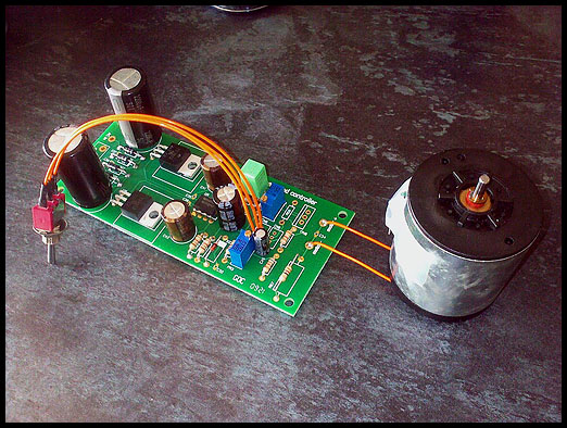
2) Here's the correlation of sketch above and the parts on the circuit boards:
- I'll update with with labelled photos of the boards and soon.
3) Build & tweaks:
4) GSC Board BOM (thanks Paul!)
[updated 30th Jan 2010]
(PCB ref) (part value) (Farnell reference)
U10 TLO71 SINGLE J-FET OP-AMP FEC 145-9699 ( or NE5534 )
U12 7812 REGULATOR FEC 108-7091
U13 7912 REGUALTOR FEC 109-5391
TR9 BD237 MEDIUM POWER TRANSISTOR FEC 994-6560
C18; C21-C26 100NF 50V 0603 X7R CAPS FOC supplied with the bare PCBs
C19 100UF 25V LOW ESR RADIAL CAP FEC 121-9466
C20 NOT FITTED but supplied with bare PCB if you choose to fit it.
C27/C28 10UF 25V TANT BEAD FEC 970-8448
C29/C30 330UF 63V LOW ESR RADIAL CAP FEC 969-2983
C31 10UF 25V RADIAL CAP FEC 812-6380
D21-D24 1N4002 RECTIFIER DIODES 200PIV FEC 146-7453
DZ1 BZX85 C6V8 ZENER DIODE FEC 984-4279
PR1/PR2 10K 25t POTS FEC 935-3704
R38/R39 IK 1% METAL FILM RESISTORS FEC 946-5170
R43/R44 47k 1% METAL FILM RESISTORS
R45 (calculated value) 1% METAL FILM
R46 4.7 OHM 3W METAL OXIDE RESISTOR FEC 950-4095 (pick a value of about 1/3 of your motor's DC resistance)
CN3 is wired to the MINI TOGGLE SWITCH on-off-on SPDT FEC 947-3432 ( wiper = centre pin of CN3 and the NO & NC contacts go to the other connections of CN3
R37; R40; R41; R42 ARE ALL LINKED OUT USING 22 SWG BTC WIRE
Switching
A Centre-Off , 2-way mini toggle speed selector switch allows the voltage reference to remain powered up and working to the optimum temperature while in the centre-off position ( otherwise there may be a slight drift for 5-15mins after switch-on) Use a fused, switched mains inlet on your case back panel for a mains-power control.
Speed choice indication
R47 is a current limit resistor for the LED speed indicator select for LEDs used. 3K9 was used o the proto build.
If you want to use LED speed indication then you will need to substitute the Mini Toggle from a SPDT to a DPDT. One pole will be wired to CN3 as mentioned above and the other pole will be wired to CN4. R47 is the ground resistor which is tracked on the PCB to the centre pin of CN4, the other 2 connections on CN4 are also tracked on the PCB and go to +12V and -12V respectively.
CN4 is connected this way:
How it works: when the speed is selected R47 grounds one of the LED's that is fed from the +12V supply, when the other speed is selected the other LED will light as it is fed from the -12 supply, so it is a kind of flip-flop arrangement, only one LED will remain on at any time.
One way used to run small motors under load accurately at low speed is to use a measure of current-feedback - basically, a small resistor in the 0v side of the motor return, and sense the voltage across this. It compensates for the armature's own resistance and seems to work really, really well (esp for minimal cogging at very low speed). This is not a new or original idea by any means - Ferranti, Philips and others used simple two and three-transistor variants for cheap capstan motors way back in the 60s, and the principle is older still. I used it for a diy cassette transport when a student and found it better than a 317...
Anyway, various mouldy old things were dusted-off and this knocked-up to help Si (Chopsaw) drive a OL motor. Here's a circut to play with:
From the voltage reference an opamp drives a pass transistor. Opamp is set-up as inverting gain of 1x, so the output voltage is compared with reference and motor voltage adjusted accordingly. A basic discrete voltage reg in other words.
The current-sensing bit is actually +ve feedback. If the motor is loaded, the current through it increases, which is sensed by the opamps +ve input from Rs and *added* to the voltage reg output, driving the motor harder so the current falls... R3, here '3k00' is there to get the scaling of these two feedback loops correct. In other words it controls damping in the system. As a result this resistor must be calculated for each motor/instance, based on the measured armature DC resistance and the values chosen for the two feedback resistors (above, both 10k). To make that easier here is a simple excel spreadsheet.
It may be better to use a fixed resistor plus a series trimpot for the damping setting to allow a bit of adjustment around this figure. If its far out, the motor can actually speed-up under load, or slow too easily (like normal DC reg supply) - you'll hear 'wow'. By playing around you'll find that your chosen motor feedback resistance must always be less than the motors armature reistance, or the control loop will be unstable. This example uses 4R7 for 12ohm armature (measured across the motor terminals)
None of the circuit parts are critical; make life as hard as you wish. The opamp can be anything slow and stable, NE5534 is a great place to start. Play with decoupling arangements as you like.
Because the main gain loop is inverting (and current-sense voltage is very close to 0v for small motors as low speed) this uses a split- rail supply. 7812/7912 quite good enough for supplies.
The pass transistor only needs to be NPN and allow an Ic of 500mA or more (in case the motor stalls). The NPN collector runs off the +ve rail, and could be dissipating a watt or two at stall. A TO220-cased part should be OK without heatsink.
Running off the -ve rail is the voltage reference. The 2k2 resistor feeds this about 3mA off 12v, so a 6.9v zener would be ok, an LM329 great if overkill. It's followed by a bit of filtering anyway :1K / 100uF would roll-off everything over 1.6hz - sheer brute force, really, given the reference is run off a regulated supply!
The speed-set is adjusted with trimpots. The diagram shows 10-turn parts but 22turn pots would offer finer control. You can fudge the zener value or range-set resistors as required to suit you motor (these values were set-up to suit an Origin Live one...).
Note that the filter and the trimpot are a voltage divider, so you'll see about 5v at the top of the trimpot. That's the max this can apply to the motor - if you want more, fiddle the resistors (R1/ R2 in the spreadsheet) to give the opamp some gain (increase R1 a bit over R2).
Adding a cap across R2 will reduce AC gain and probably improve performance a bit. Try 1-10uF
None of the caps matter, can use big cheap electrolytics for the filtering and bulk decoupling - just watch for polarity.
And that's about it, really.
Update: 25th Jan
Well since there are PCBs going out (post #261) here's a quick update and bug-fix:
1) the spreadsheet mentioned above has been fixed a little bit, 'save as' and have a play with the yellow boxes.
2) Here's the correlation of sketch above and the parts on the circuit boards:
- I'll update with with labelled photos of the boards and soon.
3) Build & tweaks:
- The PCB does not include for the commutation noise filter suggested by Werner that helps so much . This is easy to add 'freehand'
- In the spreadsheet update it simplifies things to run the voltage reference side at gain of -1 (R43=R44); if you need more voltage output to get your motor to the right speed, try using wire links in place of R37, R40, R41, R42, and 10K multiturn pots for the presets. If that's still not enough - rather unlikely - swap the zener for 8v2 and try again.
- R38 can usefully be reduced, to 500ohms or so. Definitely do this if you use a zener >6.9v.
- You can use 7815/7915 regs instead if you want more voltage headroom for strange motors / higher voltage zeners.
- R43, R44 values are now increased to 47Kohms. This minimises errors due to the source impedance of the voltage references, which tend to over-compensate the motor by effectively making R45 up to 7% too small. More detail is given in posts #337 and #339
- If you get speed variation or audible wow, increase your R45 in small increments - start with +5%
- Other minor items we can sweep-up in thread / [updates to be added].
4) GSC Board BOM (thanks Paul!)
[updated 30th Jan 2010]
(PCB ref) (part value) (Farnell reference)
U10 TLO71 SINGLE J-FET OP-AMP FEC 145-9699 ( or NE5534 )
U12 7812 REGULATOR FEC 108-7091
U13 7912 REGUALTOR FEC 109-5391
TR9 BD237 MEDIUM POWER TRANSISTOR FEC 994-6560
C18; C21-C26 100NF 50V 0603 X7R CAPS FOC supplied with the bare PCBs
C19 100UF 25V LOW ESR RADIAL CAP FEC 121-9466
C20 NOT FITTED but supplied with bare PCB if you choose to fit it.
C27/C28 10UF 25V TANT BEAD FEC 970-8448
C29/C30 330UF 63V LOW ESR RADIAL CAP FEC 969-2983
C31 10UF 25V RADIAL CAP FEC 812-6380
D21-D24 1N4002 RECTIFIER DIODES 200PIV FEC 146-7453
DZ1 BZX85 C6V8 ZENER DIODE FEC 984-4279
PR1/PR2 10K 25t POTS FEC 935-3704
R38/R39 IK 1% METAL FILM RESISTORS FEC 946-5170
R43/R44 47k 1% METAL FILM RESISTORS
R45 (calculated value) 1% METAL FILM
R46 4.7 OHM 3W METAL OXIDE RESISTOR FEC 950-4095 (pick a value of about 1/3 of your motor's DC resistance)
CN3 is wired to the MINI TOGGLE SWITCH on-off-on SPDT FEC 947-3432 ( wiper = centre pin of CN3 and the NO & NC contacts go to the other connections of CN3
R37; R40; R41; R42 ARE ALL LINKED OUT USING 22 SWG BTC WIRE
Switching
A Centre-Off , 2-way mini toggle speed selector switch allows the voltage reference to remain powered up and working to the optimum temperature while in the centre-off position ( otherwise there may be a slight drift for 5-15mins after switch-on) Use a fused, switched mains inlet on your case back panel for a mains-power control.
Speed choice indication
R47 is a current limit resistor for the LED speed indicator select for LEDs used. 3K9 was used o the proto build.
If you want to use LED speed indication then you will need to substitute the Mini Toggle from a SPDT to a DPDT. One pole will be wired to CN3 as mentioned above and the other pole will be wired to CN4. R47 is the ground resistor which is tracked on the PCB to the centre pin of CN4, the other 2 connections on CN4 are also tracked on the PCB and go to +12V and -12V respectively.
CN4 is connected this way:
- Centre pin goes to the join of a pair of back to back LED's, the other side of these LED's goes to the wiper of the spare pole on the mini toggle
- The other 2 pins of CN4 go to normally open and normally closed contacts of the spare pole of the mini toggle, it doesn't matter which way round you wire them.
How it works: when the speed is selected R47 grounds one of the LED's that is fed from the +12V supply, when the other speed is selected the other LED will light as it is fed from the -12 supply, so it is a kind of flip-flop arrangement, only one LED will remain on at any time.