
Dowser
Learning to bodge again..
I bought a Densen B-400 Plus earlier this year (see here). Got it cheap as it didn't read discs reliably - disc spin motor needed a drop of oil. But I also noted a crack in the plastic sled rail of the mech, which caused 2 intermittent skips as laser passed over it in a few weeks of listening. So, new laser unit needed.
These early Densen players use the Sony KSS-213c mech - so readily available, and still cheap. I bought one from Aliexpress (this one), CHF 16.50 at the time.
Swapping is fairly straightforward, but with a few gotcha's;
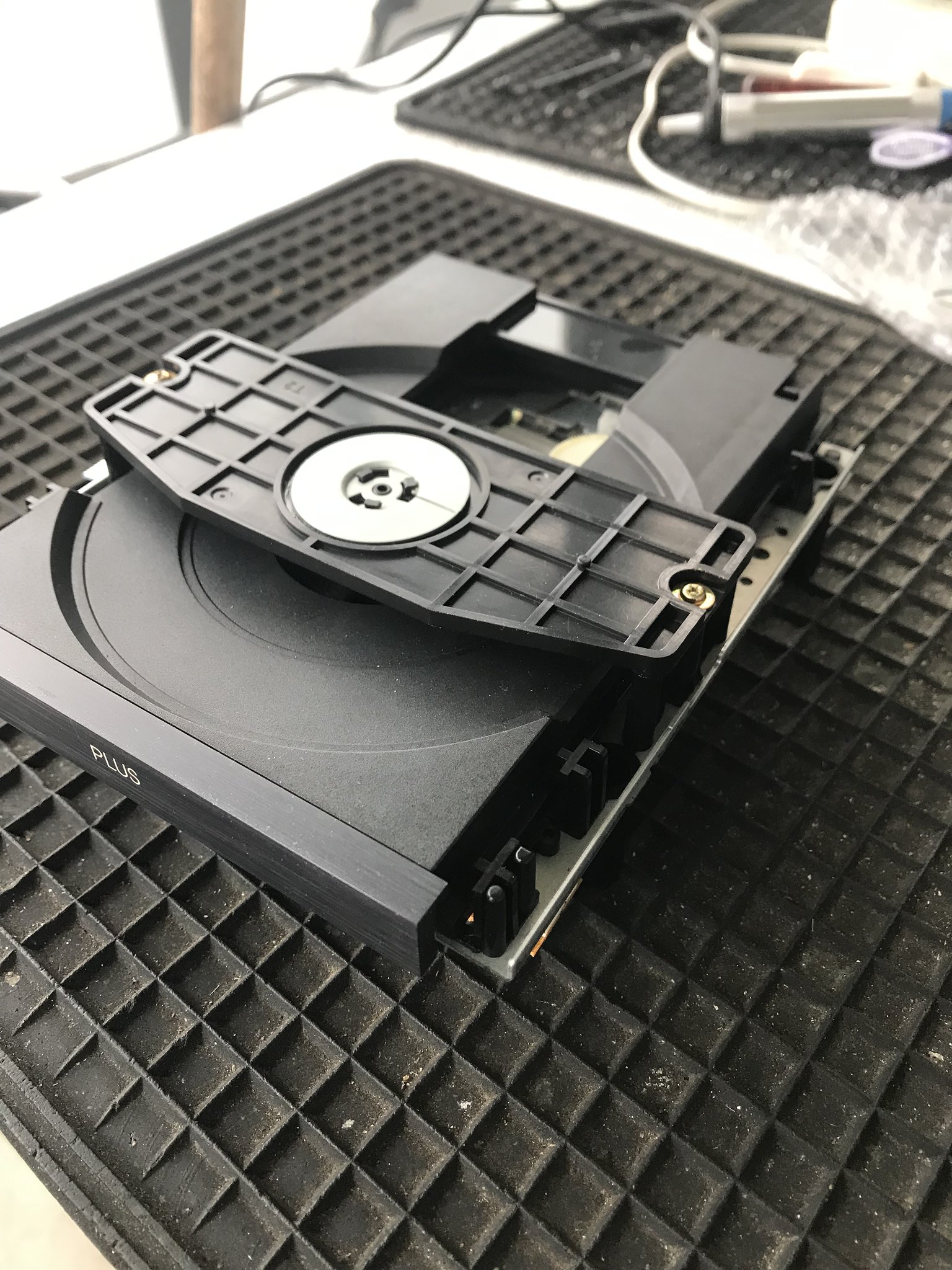
1. Remove 4 large Philips torx screws on bottom side (you will need both large and small Philips torx drivers for this), turn player back over, slide top cover forward and lift it off tilting it toward you. Carefully unplug the front display connector so you can remove top cover.
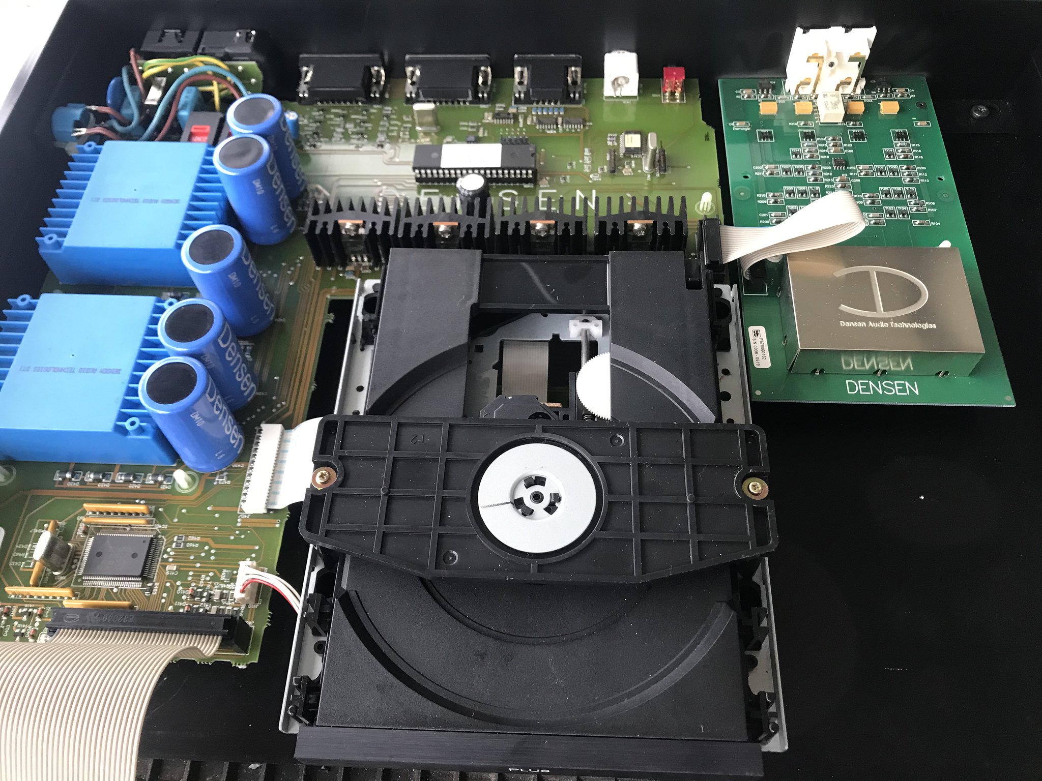
2. You now have this
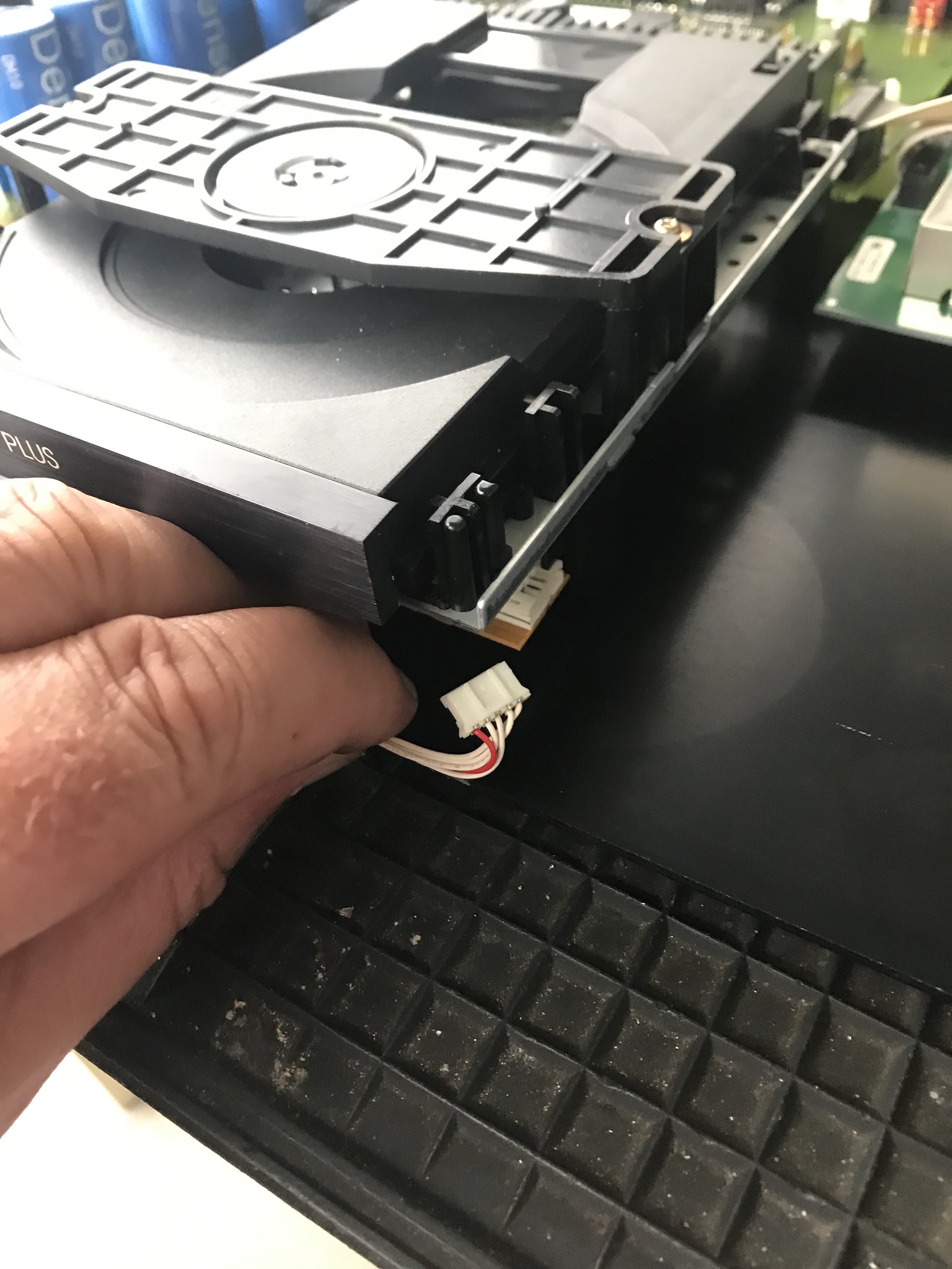
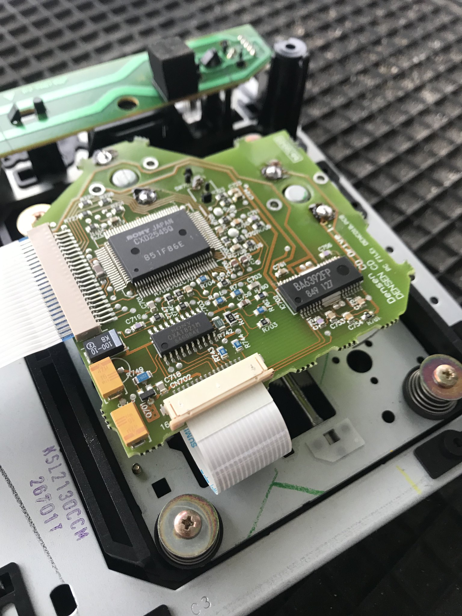
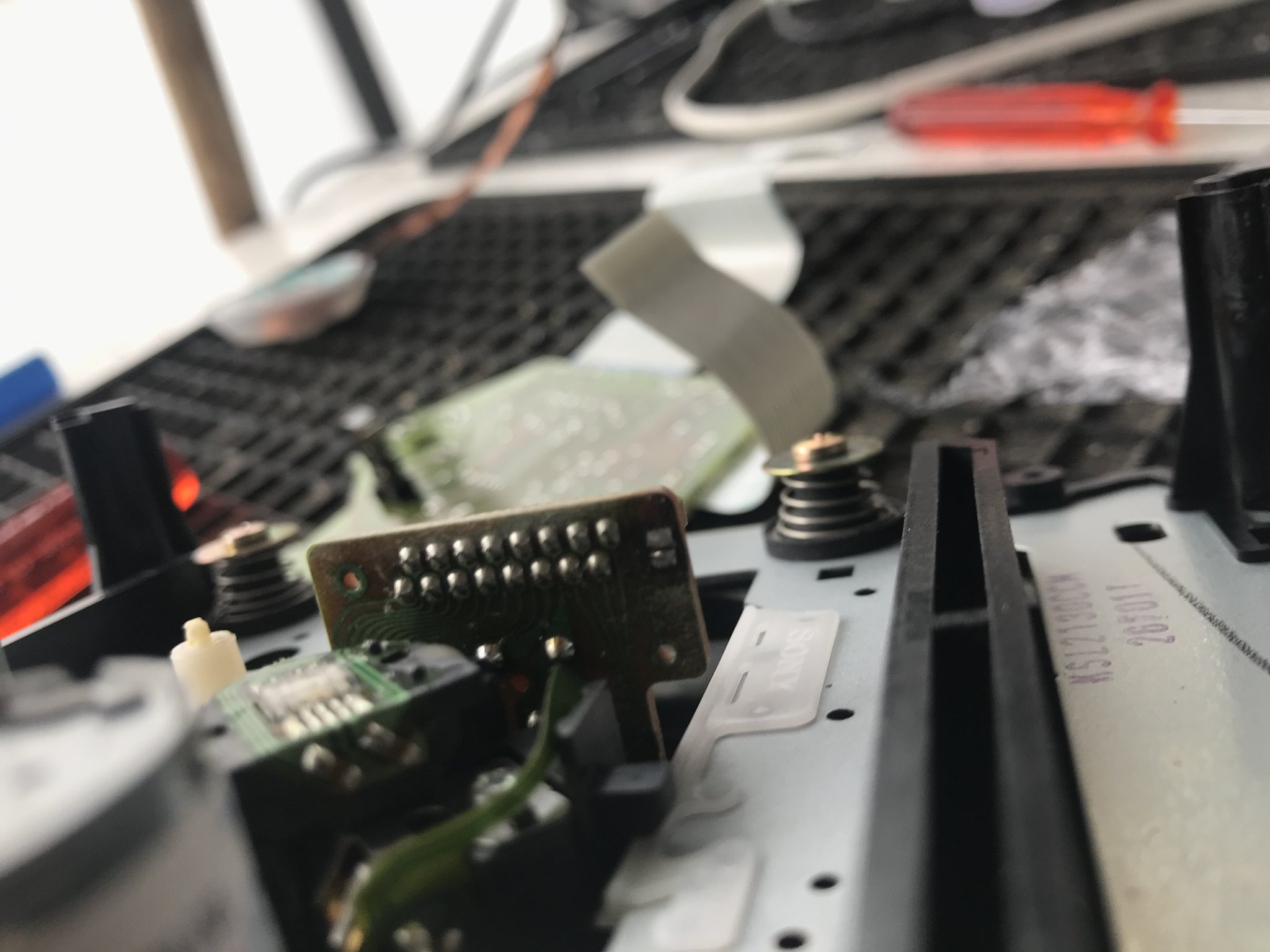
Remove this connector
And this white ribbon cable, then undo the four 2.5mm allen bolts
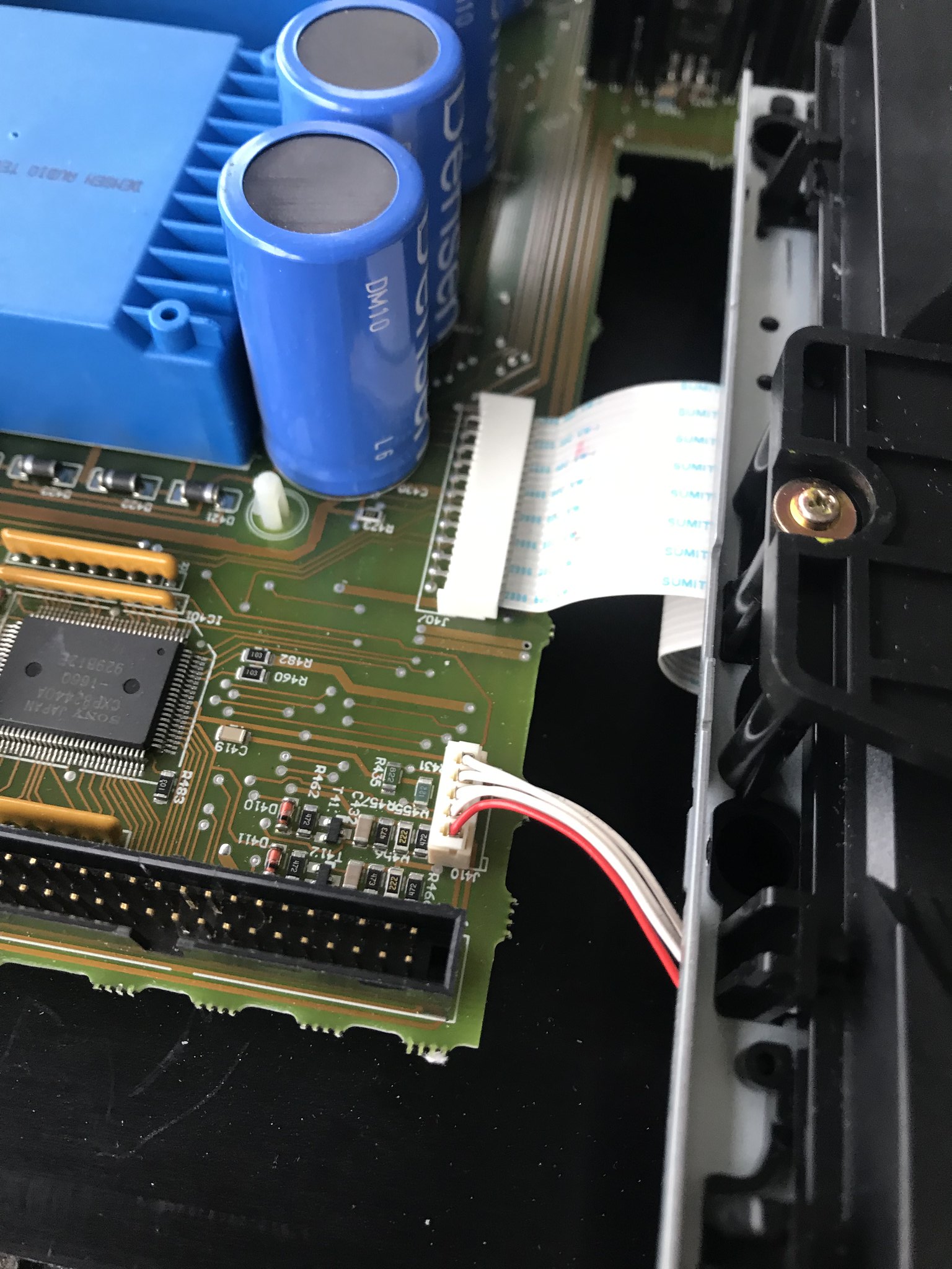
Do not lose the 4 washers between mech and chassis as you lift out the mech")
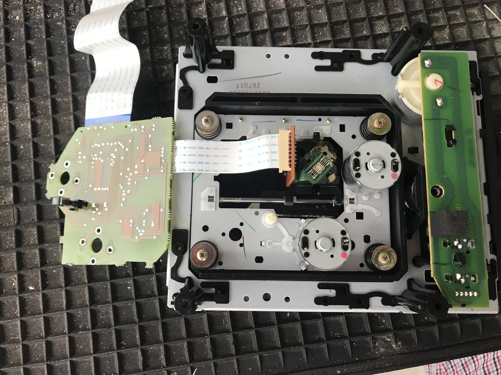
3. Now you have the mech free
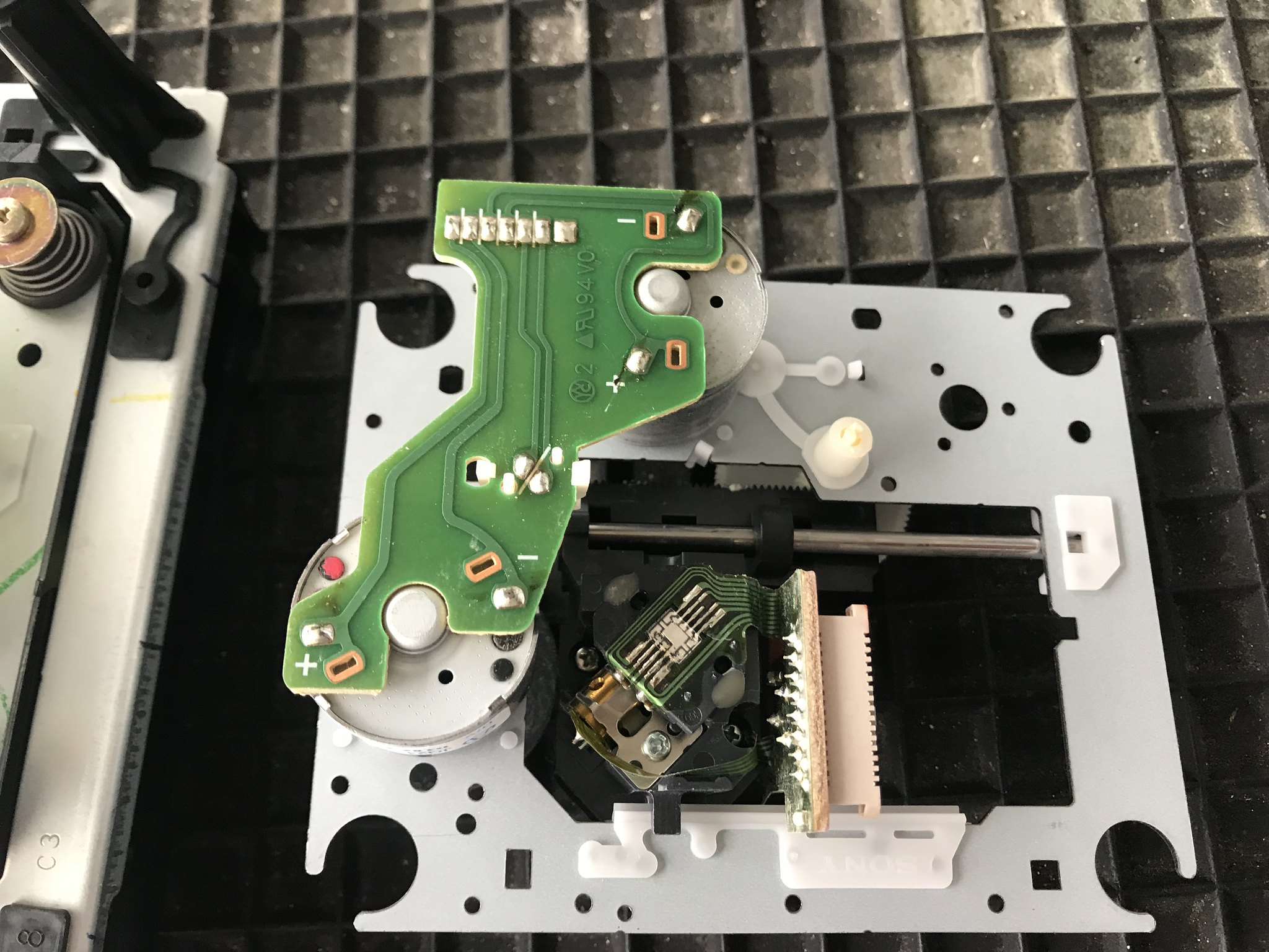
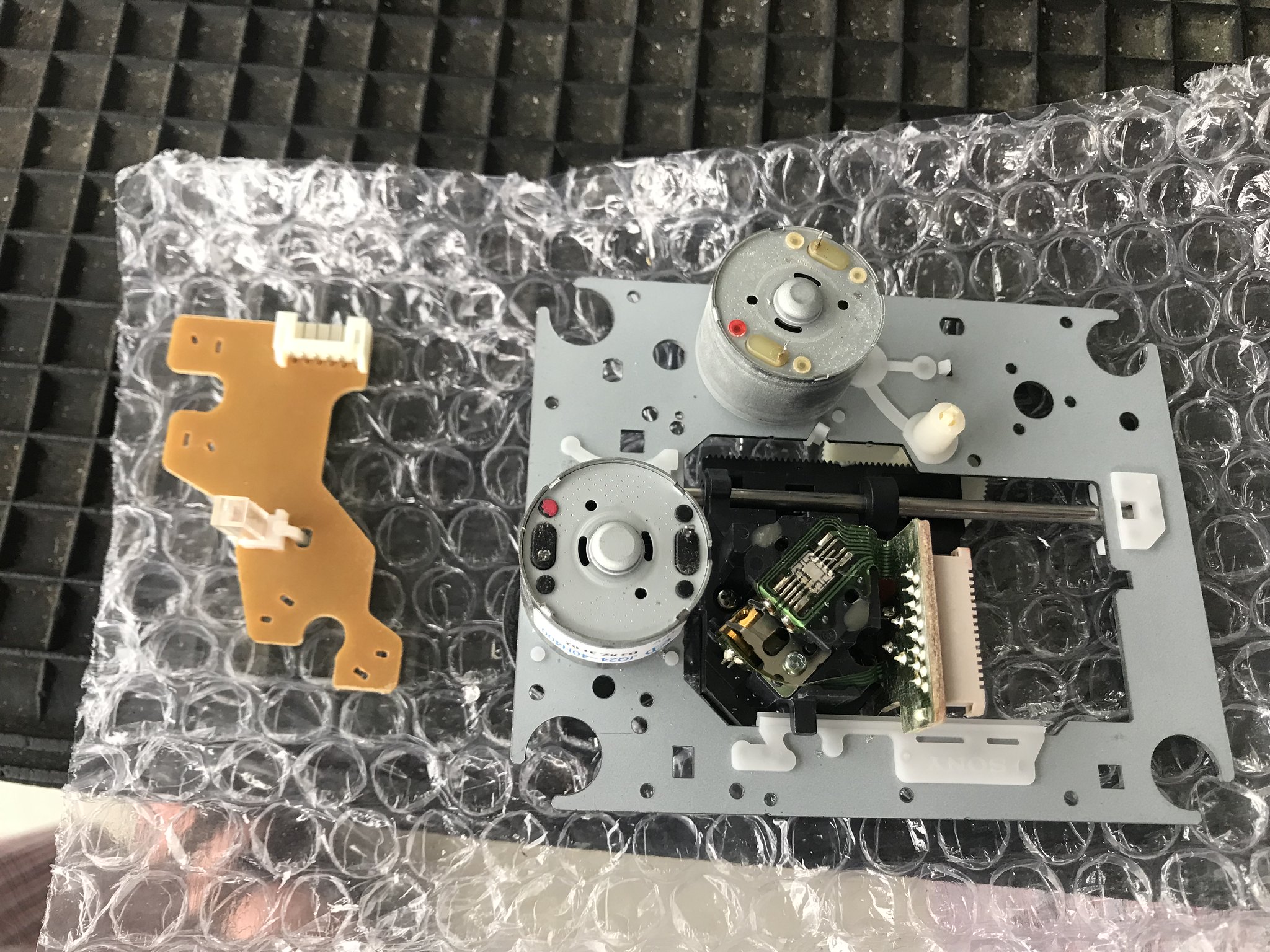
Turn it over and desolder the 4 motor connections (spin and sled motor) to the custom Densen servo board (that your replacement mech will not have!)
This can be a bit shitty - Densen used a qualilty through whole PCB...but make cleaning solder off these joints difficult. I used solder sucker then a jewellers screwdriver under edge of PCB while slowly prising board off - be careful, there are 4 joints, go slow
Then you have this;
4. Now desolder the 4 motor connections on the PCB from your replacement 213c mech (much easier, single sided PCB), and lift it off
5. Now remove the naked Sony mech from the Densen assembly - 4 screws with washers and springs. Note the springs closest to front of mech (black) are much stronger, do not mix them up. Also when re-assembling, make sure springs are properly fitted into the rubber bushings
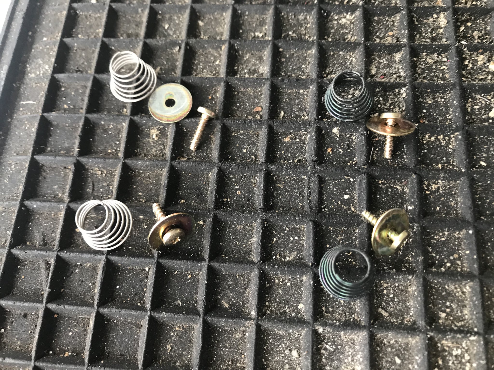
Lift off mech, and transfer the rubber bushes to your new mech
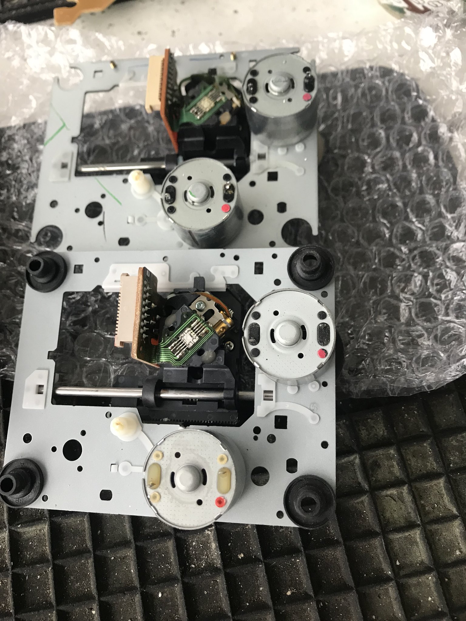
6. Before going any further - check the orientation of the new mech's sled motor pins compared to the original. On the one I got they were different. No problem, remove the 2 sled motor screws and you can turn the motor around (it has multiple mounting points)
Before
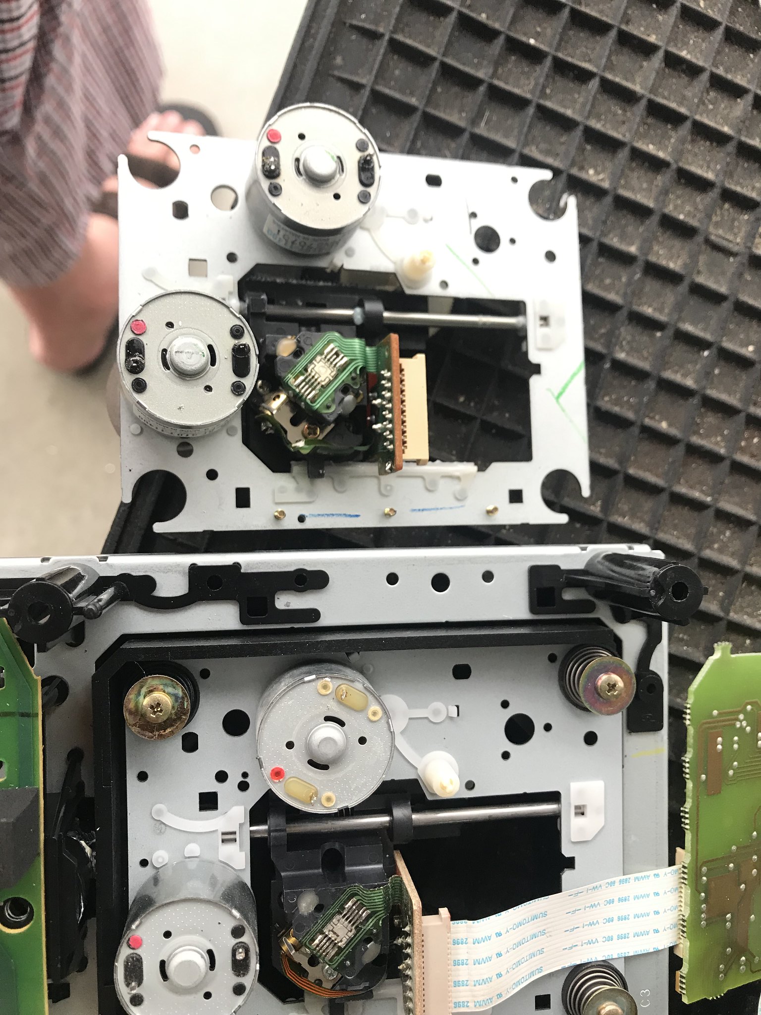
Mount screws removed
Correctly aligned
7. Home straight - re-assembly. Do *not* forget to remove the solder blob protecting the new laser from static - here it is removed
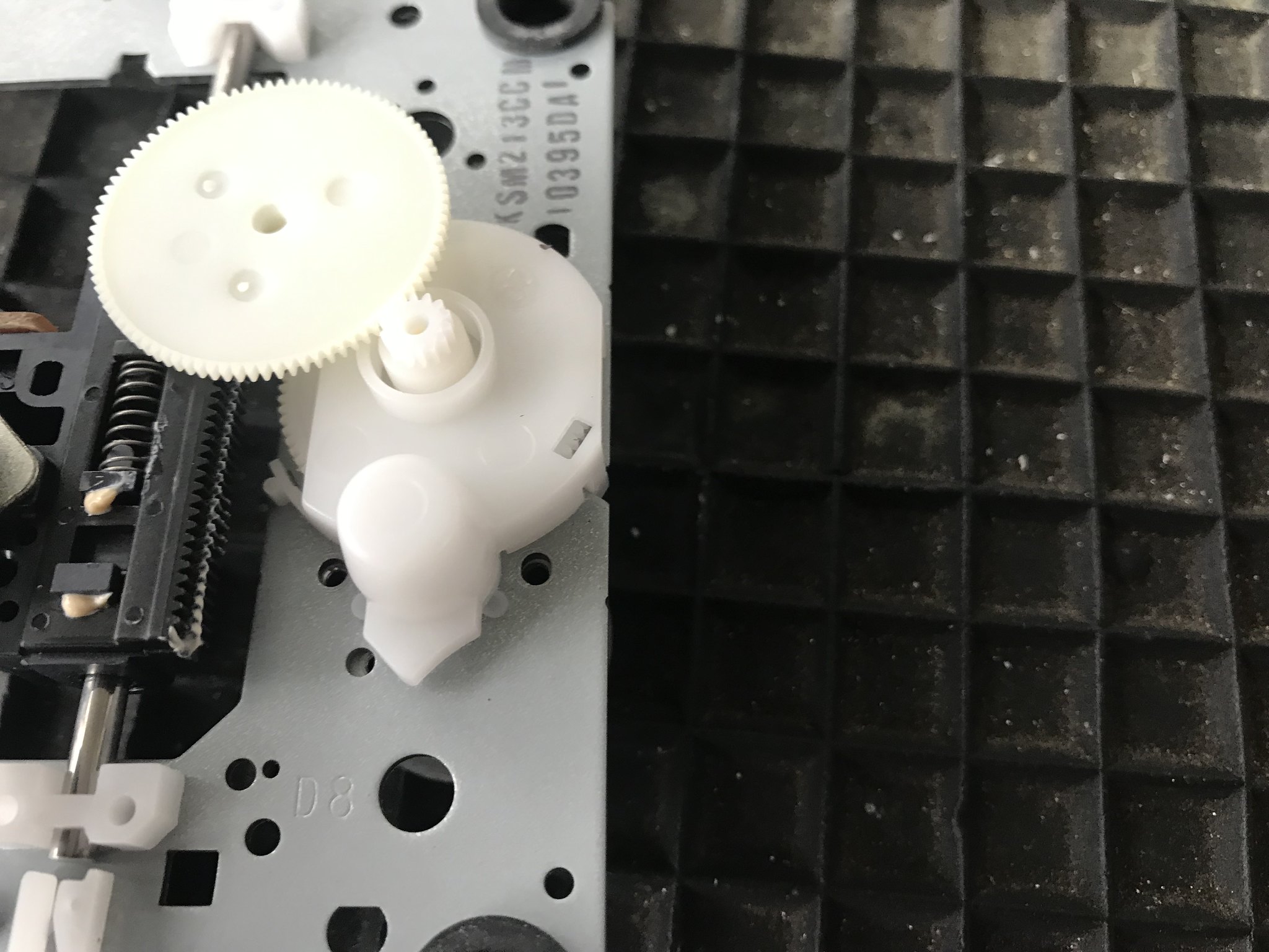
I would also advise winding the laser sled toward the middle of the rail carefully using the big white cogged wheel (so switch on Densen servo PCB does not foul).
8. Rather than fully re-assemble to test, I removed the front control PCB from outer cover - but I also wanted to check a few other things, so wanted to confirm laser was working first. Takes a bit more time...if the new laser works...otherwise will certainly p*ss you off Be careful nothing can short on the pcb - here's how I tested it
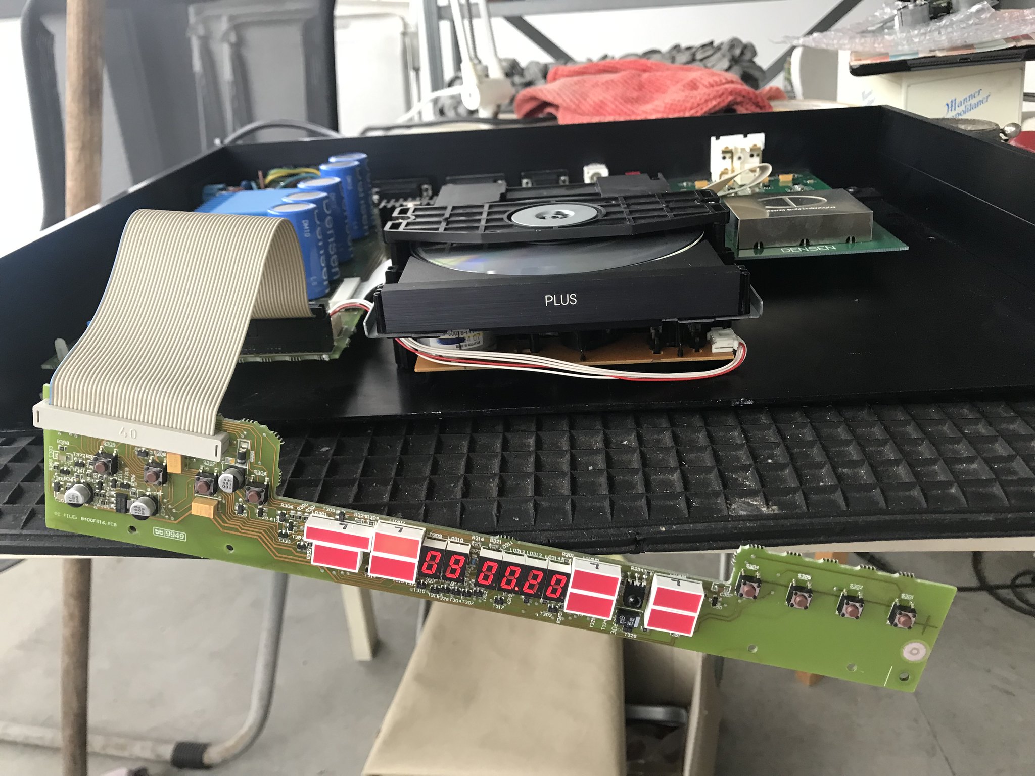
Yay - £15 replacement laser
As I mentioned, I replaced the laser because of a crack in a sled rail - you can just see it here
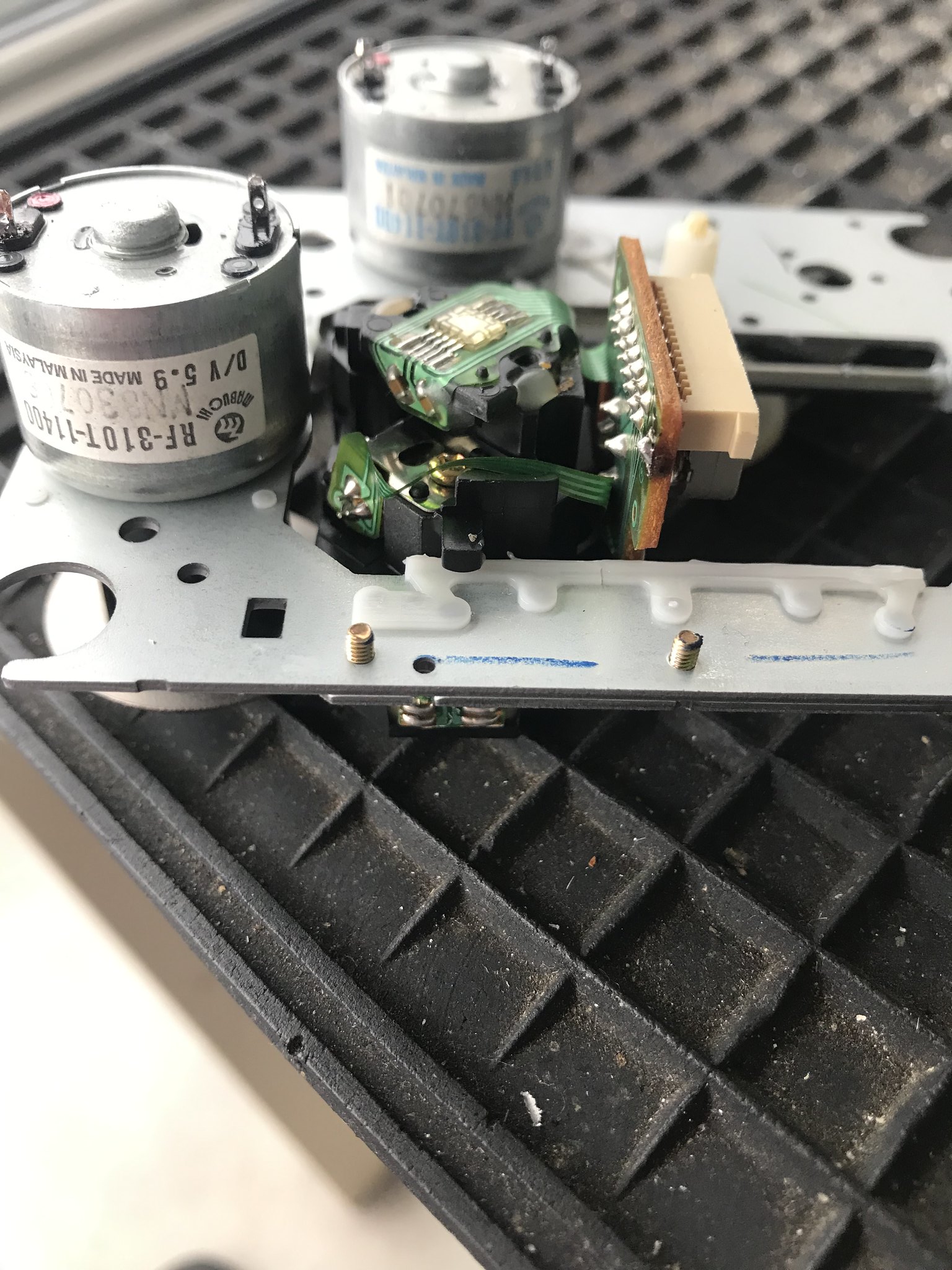
You can just see the rail crack to left of PCB board - in my youth I had a few of these as root cause for intermittent skips when I was a repair guy.
It means I can resell it now with a good spare laser, spin and sled motors
You'll see from above post, I had a slight tizz when nothing was playing originally. So I also check specs of the Densen caps - they're all within 2.5% of 10kuF. There was one other 1kuF cap between regulators and CPU that was over 5% under. I replaced it. But also while removing main PCB the mains live connection popped straight off the filter due to a bad solder joint
Brown wire closest to transformer, now re-soldered
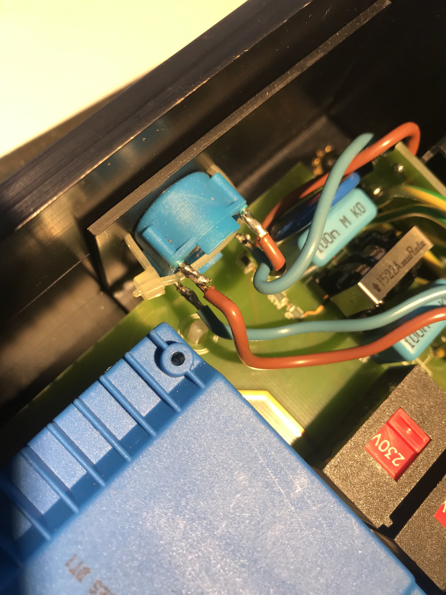
One or the other was causing the tizzing, all good now
Great players, keep them alive!
Richard
These early Densen players use the Sony KSS-213c mech - so readily available, and still cheap. I bought one from Aliexpress (this one), CHF 16.50 at the time.
Swapping is fairly straightforward, but with a few gotcha's;
1. Remove 4 large Philips torx screws on bottom side (you will need both large and small Philips torx drivers for this), turn player back over, slide top cover forward and lift it off tilting it toward you. Carefully unplug the front display connector so you can remove top cover.
2. You now have this
Remove this connector
And this white ribbon cable, then undo the four 2.5mm allen bolts
Do not lose the 4 washers between mech and chassis as you lift out the mech
3. Now you have the mech free
Turn it over and desolder the 4 motor connections (spin and sled motor) to the custom Densen servo board (that your replacement mech will not have!)
This can be a bit shitty - Densen used a qualilty through whole PCB...but make cleaning solder off these joints difficult. I used solder sucker then a jewellers screwdriver under edge of PCB while slowly prising board off - be careful, there are 4 joints, go slow
Then you have this;
4. Now desolder the 4 motor connections on the PCB from your replacement 213c mech (much easier, single sided PCB
), and lift it off
5. Now remove the naked Sony mech from the Densen assembly - 4 screws with washers and springs. Note the springs closest to front of mech (black) are much stronger, do not mix them up. Also when re-assembling, make sure springs are properly fitted into the rubber bushings
Lift off mech, and transfer the rubber bushes to your new mech
6. Before going any further - check the orientation of the new mech's sled motor pins compared to the original. On the one I got they were different. No problem, remove the 2 sled motor screws and you can turn the motor around (it has multiple mounting points)
Before
Mount screws removed
Correctly aligned
7. Home straight - re-assembly. Do *not* forget to remove the solder blob protecting the new laser from static - here it is removed
I would also advise winding the laser sled toward the middle of the rail carefully using the big white cogged wheel (so switch on Densen servo PCB does not foul).
8. Rather than fully re-assemble to test, I removed the front control PCB from outer cover - but I also wanted to check a few other things, so wanted to confirm laser was working first. Takes a bit more time...if the new laser works...otherwise will certainly p*ss you off
Be careful nothing can short on the pcb - here's how I tested it
Yay - £15 replacement laser
As I mentioned, I replaced the laser because of a crack in a sled rail - you can just see it here
You can just see the rail crack to left of PCB board - in my youth I had a few of these as root cause for intermittent skips when I was a repair guy.
It means I can resell it now with a good spare laser, spin and sled motors
You'll see from above post, I had a slight tizz when nothing was playing originally. So I also check specs of the Densen caps - they're all within 2.5% of 10kuF. There was one other 1kuF cap between regulators and CPU that was over 5% under. I replaced it. But also while removing main PCB the mains live connection popped straight off the filter due to a bad solder joint
Brown wire closest to transformer, now re-soldered
One or the other was causing the tizzing, all good now
Great players, keep them alive!
Richard