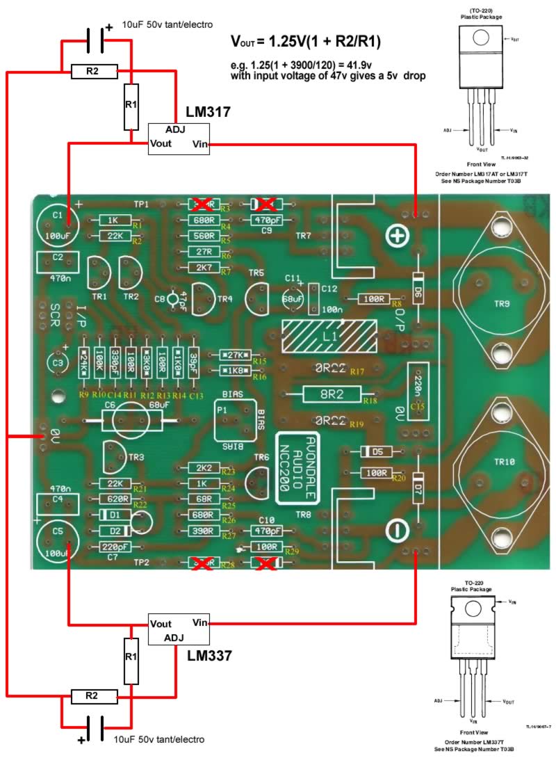
Richard - nice diagram, and that will work fine.
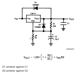
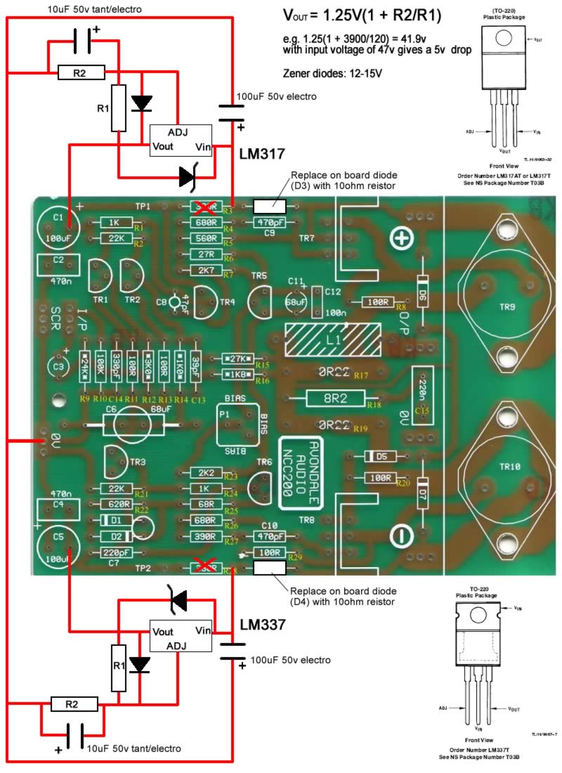
Do add a protection diode from the junction of R1-R2 in each case, reverse-biased back to the input pin. At higher voltages it will stop the charge on the 10uF bypass cap killing the reg from injection into Vadj if the input supply falls faster than c1 can discharge (possible with a large value of R2). NB LM337s are really quite sensitive to this, IME.
I'd also recomend to add a 1w zener diode, say 12 or 15v, reverse-biased from input pin to output. As switch-on this can avalanche and ensure the 3-pin reg is never exposed to more than 12-15 v across it (datasheet limit is 37v of course) - but once the reg is running it is totally out of circuit. With output cap at low voltage/ charging at switch-on you might get >35v transients across the reg (NB this trick becomes essential if you go much larger than 10uF.) It also acts as a regular forward bised diode at switch-off , so teh reg cannot endup ,again, reverse-biased.
Both my SOP for using 3-pin regs at higher voltages, and cheap protection. You can use 317s well over 300v with such measures
")

 Pair of Hackernaps