advertisement


QUDOS - the brilliant new amplifier boards from Avondale

I wonder how much difference the new front end regs make? I’m sticking with the old VBEs for the time being.
Les made my Voyagers with the HCR reg on the front end, there was quite a difference compared to a VBE’d voyage clone, although apart from NCC200 there wasn’t a great deal in common.

Timing and control are often banded about, but these amps have it all imo :D
 
Thanks DDD. Even if there is a leap in sq I think I'll stick with the old VBEs as I'm slowly getting the bits and pieces together to build my 300s. I'll just have to slum it for a while :D
 
Having been responsible for the NCC200 BOM for a number of years I have been asked, via PM, if I will produce a BOM for the NCC220 (Qudos). As many of you will know I have retired from constructing, repairing and upgrading equipment for others although I still do some work for myself. I continue to post on PFM when I feel I have advice that may help other members. I'm very busy dealing with other matters at present and am not in a position to produce and maintain the required BOM.

The changes between the NCC200 and NCC220 are small in number but significant in their importance. Most of the components are common to both boards. I wonder if anyone else here would take on the task of producing the NCC220 BOM? I'll be happy to send them the NCC200 BOM as a starting point.
 
I'm working through a couple of things on my boards at the moment and as part of that am going through the circuit and crosschecking. Way back when, I did a labelled board and circuit image with all the resistors numbered. Would that be of help for this if I did a new version for the Qudos?
 
I can put together an 'official' one for the Qudos in a spreadsheet if someone can provide me with the NCC200 BOM ... if it's useful ...

Thanks Jonathan, send me a PM with your e-mail address and I'll send you the NCC200 BOM. I'll also include the circuit diagrams for both the 200 and the 220; the latter clearly indicates most of the component changes but you also need to check for components not fitted to the 220 like the 100R resistor from the base of TR10 to the negative rail on the 200. Les never revealed the secret of the type of capacitor used at C6 to me - I suspect it's a metal-cased wet tantalum but it may even be a film type.
 
I'm working through a couple of things on my boards at the moment and as part of that am going through the circuit and crosschecking. Way back when, I did a labelled board and circuit image with all the resistors numbered. Would that be of help for this if I did a new version for the Qudos?

I think I have one Richard. I'll have a look when I get home...
 
I have one too now! Not sure if the resistor notation is the same as the BOM that misterc6 has been curating, though. Will post in a mo...
 
This is the most recent version of the circuit that I have

avondale_qudos_circuit_diag.gif


...and their location on the board
avondale-qudos-board-labelled2.jpg
 
Last edited:
Hmm, my cct diagram is different...

This is the original scan, the values in red are to what I've built to, the green values for R4, C9, R5, R26, R27 and C10 are from Richard's scan above.

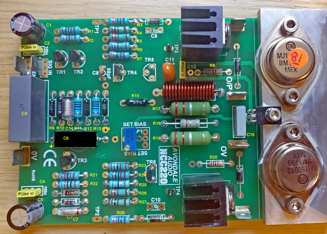
NCC220 Change to BOM by Garf Arf, on Flickr

Location My build Richard's scan
R4, R27 100R 27R
C9, C10 470pf 100n
R5, R26 220R 15R

In fact, looking at the built PCB it has been built with my build's values. Has LesW tweaked the cct?

And R18, the 8R2 in series with C15 on the output has been changed, by hand, to 6R8.
 
Well, I am waiting for a bit of info from Les, but he's off for a week so it's probably best to hold fire and see what the latest version is. It may well be that these are just different "flavours".
 
I’m wondering how big the heat sink for the 220 needs to be. I powered up my first finished 220 this morning and I couldn’t get enough current draw without the heat sink getting quite warm. T5 is doing its job and was backing the current off as the heat sink was getting warmer so I bolted the C spreader to a large lump of thick aluminium plate. The whole lot gets warm but not unduly so even though I’m only drawing 112mA. T5 is still trying to pull it down so do I need even more heatsinking or do I go for broke and keep turning the bias up? Build is the same as chiily’s diagram a couple of posts back.
 
I’m wondering how big the heat sink for the 220 needs to be. I powered up my first finished 220 this morning and I couldn’t get enough current draw without the heat sink getting quite warm. T5 is doing its job and was backing the current off as the heat sink was getting warmer so I bolted the C spreader to a large lump of thick aluminium plate. The whole lot gets warm but not unduly so even though I’m only drawing 112mA. T5 is still trying to pull it down so do I need even more heatsinking or do I go for broke and keep turning the bias up? Build is the same as chiily’s diagram a couple of posts back.

I found the heatsinks to get quite warm. I have the speaders bolted to a thick Al case and that does the biz. One I have found is that they don't seem to get any warmer when playing music hard.
 
Ok thanks chilly. The ally base plate in each my Voyagers is 3mm thick and if I put a 10mm thick ally plate say 120 x 320mm under the 220 and the vbe board I’m hoping that should do it. I’m not bothered about the heat sink getting hot tbh, I just want the devices to pull more current. Can the sensitivity of T5 be reduced at all?
 
I built mine to the values on the board which apart from the input filter are the same as my NC200, I run 120mA bias on my voyager version it does not get any hotter by touch than the NC200 driven hard its just hot all the time.I could not get more than 120 mA on one of the board's so stuck at that.
 
I've been running mine for a year, as shown in the first few posts of the thread but now with custom Canterbury Windings transformers, at 120mA as mono amplifiers in two Naim shoebox cases. The cases are just pleasantly warm to the touch and the performance is superb. I built them to the circuit posted by chiili with 100nF films on the front-end decoupling and C12. C12 is missing from both circuits shown above (and the NCC200 circuit) and is in parallel with C11 between emitter and collector of TR5. I've seen quite a few boards with 220nF films in these three positions which is perfectly OK.

It looks as if Les has tweaked the networks on the bases of TR7 and TR8 and RichardH is waiting for Les to return from holiday to confirm this.
 
Thanks, Richard! Last week, Les sent me the same circuit diagram as you posted in #369 and said to follow the circuit, not what's on the PCB.

BTW, I noticed that R2 on your PCB is not 1K as on the circuit diagram.
 
BC546s (TR1, 2, and 3) come in 3 hfe ranges (A, B, and C). What's the recommendation for which range to use?
 
Thanks, Richard! Last week, Les sent me the same circuit diagram as you posted in #369 and said to follow the circuit, not what's on the PCB.

BTW, I noticed that R2 on your PCB is not 1K as on the circuit diagram.

The built PCB doesn't have the changes in the cct diagram from what I can make out. For example R4 looks to be 100R and not 27R.


advertisement


Back
Top