advertisement


Philips CD160 not working

Thanks Mike,
Looks like I have some work to do then ;). As you say, caps are a personal thing and despite what some say, I can hear the difference between cap types on psu decoupling adjacent to op-amps etc. Tried Silmic ii's as feed-back caps on a phono stage some years ago but found them too dark and could never be sure they had burned-in (reports at the time suggested >200hrs!). Op-amps have generic 47uF caps, now fed by gyrators (cap multipliers) on #1 machine.
Listening with headphones last night to both machines (I have about 4 pairs of CDs so I can switch back-and-forth) the #1 machine has more top-end but actually sounds more natural than the #2 machine which sounds slightly plasticy with a bit of falseness. Any opinions on the muting circuit after the output coupling caps many players have, including Rotels etc. and does this adversely affect the sound to any degree?
Cheers,
AP
 
Usually muting transistors can just be removed. The only downside is that you might get some weird noises when selecting tracks. They can always be put back in if there's a problem.

In my old Arcam project I removed the muting transistors and had zero issues with noises, it was completely silent between tracks.

Better CD players use muting relays.

What opamps are you using?
 
Mike,
The original LM833s as I wanted to "squeeze" the best out of it without resorting to multiple extra lm317/337 psus, fancy op-amps etc. Modded machine (#1) has:
2.2uH inductor feeding 220uF Pana FM//.1uF X7R for SAA7220 from main +5Vdc supply, which reduced the noise at the input pin by about 50%. The TDA1541 has standard 10R+47uF on -5Vdc and -15Vdc and I have ALWSR with generic 47uF (1R ESR for stability) on +5Vdc. These three also have original SMD bypass underneath. Was considering trying 27R+220uF on -5Vdc as this will give about 1Vdc drop (from -6V supply, thus giving 9.9Vdc difference between -5 and -15) and vastly improved noise rejection as the corner freq is about x10 lower. Funnily enough I was measuring some "Nover" brand 220uF caps I have and the ESR was 0.15R so was going to use one of those.
AP
 
I highly recommend giving the SAA7220 its own dedicated voltage reg. ;)

I've just a added dedicated 7805 for the SAA7220 in my Philips CD960 (aka Marantz CD94) and it made a very worthwhile difference. Some years ago a built a dedicated PSU for the SAA7220 in my ultra-modded Arcam Alpha 5 and it was the single biggest upgrade I ever made to that player.

The trick to the SAA7220 decoupling is to keep the loop area as small as possible and on the SAA7220 the loop area is always bigger than ideal because the power and ground pins are on opposite corners! No point in fitting a high frequency bypass decoupling cap away from the IC, it won't help.

Martin Clark recommends a 47uF Oscon with its legs stretched wide apart and soldered under the PCB in a corner to corner to fashion between the +5v and ground pins. I've used this set up and can confirm it works very well. I can also recommend an axial 0.1uF X7R soldered in the same way in conjunction with a larger (say 100uF) quality electro (e.g. Rubycon ZLH).

I've not had much experience with LM833's but if they're the original factory fitted opamps they're probably just fine. I just wanted to make sure you hadn't fitted some ultra-fast super duper opamps as that could easily be unstable and oscillating.

In my favourite CD player I finally settled on the JRC5532DD and JRC5534D after spending countless hours and a huge amount of money rolling fancy boutique opamps.
 
Mike,
LM833 original factory fitment. Yes, been reading your thread on the Sony 337ESD with great interest and scouring other related threads too for info / wisdom. Know what you mean about the distance between opposite corners of the SAA7220 so will try something along the lines you have suggested along with a 7805 or LM317 depending on what I have....
Cheers again,
AP
 
Dry grease on the rails,it often improves when a unit warms up it typically effects the early or late tracks on the cd where the grease collects.
 
My apologies i've cured many skipping cdp's that way...just looking at my 160 and realised it's probably the only cdp i've never had the lid off
 
After doing the mod to the -15V and -5V supplies to the TDA1541: (https://pinkfishmedia.net/forum/threads/arcam-and-the-tda1541.29579/page-4#post-3592567) which makes an incredible difference and is well worth doing, I was probing around with the scope and noted that no matter where I measured from on the earth plane of the board to the earth plane on the SAA7220 that it was noisiest near to pin 12 (the earth point) and looking at the circuit layout in the service manual revealed that the 11.3 MHz crystal oscillator (connected to pins 10 and 11 of the SAA7220) is also connected to the earth plane via a pair of 47pF chips, right beside pin 12. These are dumping about 50mV at 11.3 MHz onto the earth plane. Can these simply be removed or is there a better scheme for this? In the meantime I will have a look at some service manuals for other machines and see what other manufacturers do.
Best,
AP
 
The two 47pF caps are essential, since these in conjunction with with the crystal (and a 'gate' in the SAA7220) actually form the oscillator circuit. So don't worry about the HF you are seeing here - it is necessary.
 
Martin,
Thanks for the swift response. I see that Rotel (RCD855 and RCD955) and Marantz (CD65) use pretty much the same circuit so been surfing the internet and as you say these are part of the resonant circuit. However, is it permissible to decouple the centre of the capacitor pair with a ferrite bead or is that likely to cause issues?
Thx,
AP
 
You can't really do anything about it - sorry; enough ferrite to make things quieter will also stop the clock...

PS don't overlook the loop-area of your o'scope probe is probably doing the pick-up - that 4-5" flying lead, to the probe tip, 'sees' everything at HF that radiates. In other words, what you are seeing trying to measure across areas of the earth plane, probably isn't noise in the earthplane...
 
OK Martin. Was just concerned about trying capacitors across the supply pins of the SAA7220 because of them injecting this noise into the +ve supply pin, but I understand you are saying that this is a measuring artifact due to the loop area of the 'scope probe and associated probe earth. Useful to know, thanks for that.
Best,
AP
 
Was pondering how crystal oscillators work last night and Martin's comment about loop area as well as simultaneous charging / discharging of caps (e.g. on power supplies but particularly oscillators) producing notable current flows between the "common" of these caps whilst looking at the circuit layout under the SAA7220 adjacent to pins 10 to 12. I have spotted something with the layout of the two 47pF caps on the x'tal where they meet the earth plane that needs further investigation. It would appear that all the current that flows back-and-forth between these two caps flows in and out of a narrow trace that connects the local earth plane of the SAA7220 back to the main ground plane on the top-side of the circuit board. This weekend I am hoping that re-positioning one of these caps may yield improvements in the "ground-bounce" that (I think) I am seeing.
 
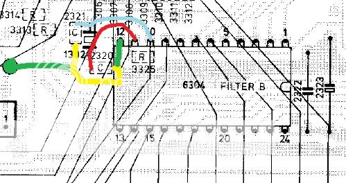
Now I have sorted my photobucket a/c, some images. Below is a cropped view of the circuit around the SAA7220 on the CD160:
CD160%20SAA7220%20edit.jpg

The blue and red traces are from pins 10 and 11 respectively and go to the crystal. The yellow line is the common of the two 47pF caps from crystal to earth plane and as you can see, the current that flows between these is via the local earth connection for the chip (green) back to the upper surface copper plane . I think that this is adding a lot of noise to the local earth plane so I am hoping to modify like this:
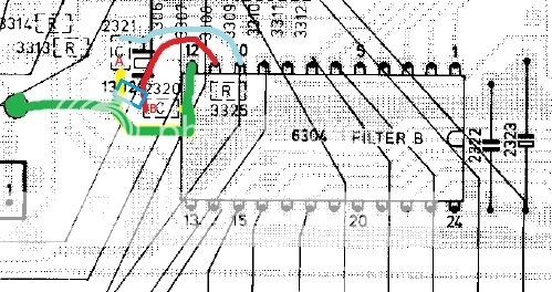
CD160%20SAA7220%20edit%20B1.jpg

So that the 47pF cap at B is moved to the blue box position so that the length of the common connection (yellow) is reduced and the earth path (green) should be much cleaner as it is no longer carrying this 11MHz current.
 
The above mod made no measurable (or audible) difference. :(
However, I removed the earth connection (where the trace under the circuit board connects to the earth plane, green dot left of above image) and instead connected the negative wire of the electrolytic (2323 in above picture) back to the ground plane as this is much closer to where the 5V supply trace is. That gave a small but noticeable improvement in clarity. :)
AP
 
Been doing some further reading and (completely by accident) found that the Marantz CD273 is essentially the same mother board and mechanism as the Philips CD160. Uses a different display board (2 sockets rather than 1) but is essentially the same (SAA7220 / TDA1541) and the same board. The only difference I can see with a cursory once-over is the presence of a small add-on circuit board called "debounce" which is fed by the +5V supply and 0V and goes between MUSB and SDAB (pins 23 and 7 of the SAA7220). Any ides as to the function of this?
Ta,
AP
 
One thing everyone: replace the Phillips axial cap on the laser supply. Use a BC/Vishay only.

I’ve had many players with that fault, the latest one being a mint QUAD CD66 which I got for very little because it had a bad laser.

This is important - do it.
 
Is that component 2103 the 33uF axial? If so I did all the electros ages ago. Presumable if this goes caput, blown laser?
AP
 
No. It will just cause the player to behave badly.

However, only an axial BC will do. I don’t know why, but it’s a fact. I’ve done many and it’s 100 % success guaranteed.
I’ve tried other caps, but they always cause bad behaviour.
I always buy mint Philips CDM2/4-based players with so-called toast lasers because I know they can be fixed easily. Philips lasers are very reliable. Caps less so!


advertisement


Back
Top