
You are using an out of date browser. It may not display this or other websites correctly.
You should upgrade or use an alternative browser.
You should upgrade or use an alternative browser.
NCC200 GB Build thread
- Thread starter shoom
- Start date
I've finished the board's and cap6. I'm awaiting delivery of my case but I'm a little impatient so want to hear my build working on a very low volume so I hooked up a small speaker. As soon as I connect the speaker I hear loud white noise?. If I turn up the volume I can barely hear the music through the nnoise. Both amps are the same so I assume its a common error. I checked the speaker and it works ok on another system.
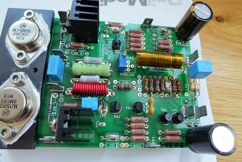
The bias current is about 36.6mA The Dc offset jumps about a bit around 35mV
Tr1 emitter is 0.65mV
Tr2 emitter is 0.63mV
Voltage across 1k Tr1 collector resistor is 0.43 mV
Pcb top pic
Pcb bottom pic
Any suggestions as to how I troubleshoot this would be greatly appreciated.
Kind Regards Damian
The bias current is about 36.6mA The Dc offset jumps about a bit around 35mV
Tr1 emitter is 0.65mV
Tr2 emitter is 0.63mV
Voltage across 1k Tr1 collector resistor is 0.43 mV
Pcb top pic
Pcb bottom pic
Any suggestions as to how I troubleshoot this would be greatly appreciated.
Kind Regards Damian
Hi,
Just wondering if there's another way to check/adjust the bias.
When I was setting mine I felt a bit uneasy having meter leads clipped onto the board/psu then powering it up.
Previously I built a P3A amp (Elliot Sounds) and that bias was measured by reading a voltage off one of the emitter resisters and using a formula to convert the reading to mA. It was easier because you took the reading by clipping your meter leads onto the legs of the component, and it felt safer to me.
Could we do a similar thing here maybe? - Just wondering.
Kind regards
Roy.
Hi Damian
The measurements look OK so may I ask how you've connected your source?
Pre?
Remember its often more haste less speed with these builds.")
On the bias measurement
Good point Roy
But
It may well be easier to measure across the emitter resistor but with 5% tolerance at best for those parts it's less accurate. The Hacker build method does indeed use the emitter resistor method but is it accurate?
Using the method with a multimeter as outlined by Les IMHO allows more accuracy which matters for this design.
I meaure bias in the following way.
1) Make up 2 x long leads with Female spade connectors at either end.
2) Fit one lead to the positive power ouput from the cap6.
3) Fit the other lead to the positive input of the NCC200 board
4) I noticed that with a little push that my multimeter probes fit inside the Female spade connectors snugly.
It’s pretty easy to measure the bias current that way without the worry of clips flying off mid measure.
Works for me
The measurements look OK so may I ask how you've connected your source?
Pre?
Remember its often more haste less speed with these builds.
On the bias measurement
Good point Roy
But
It may well be easier to measure across the emitter resistor but with 5% tolerance at best for those parts it's less accurate. The Hacker build method does indeed use the emitter resistor method but is it accurate?
Using the method with a multimeter as outlined by Les IMHO allows more accuracy which matters for this design.
I meaure bias in the following way.
1) Make up 2 x long leads with Female spade connectors at either end.
2) Fit one lead to the positive power ouput from the cap6.
3) Fit the other lead to the positive input of the NCC200 board
4) I noticed that with a little push that my multimeter probes fit inside the Female spade connectors snugly.
It’s pretty easy to measure the bias current that way without the worry of clips flying off mid measure.
Works for me
Hi Shaun,
Okay mate, fair comment. - it was just a thought.
Did you mean . . . the positive input of the NC200 board?
Kind Regards
Roy.
Okay mate, fair comment. - it was just a thought.
2) Fit one lead to the positive power ouput from the cap6.
3) Fit the other lead to the positive input of the cap6 board
Did you mean . . . the positive input of the NC200 board?
Kind Regards
Roy.
337alant
Negatively Biased
I've finished the board's and cap6. I'm awaiting delivery of my case but I'm a little impatient so want to hear my build working on a very low volume so I hooked up a small speaker. As soon as I connect the speaker I hear loud white noise?. If I turn up the volume I can barely hear the music through the nnoise. Both amps are the same so I assume its a common error. I checked the speaker and it works ok on another system.
The bias current is about 36.6mA The Dc offset jumps about a bit around 35mV
Tr1 emitter is 0.65mV
Tr2 emitter is 0.63mV
Voltage across 1k Tr1 collector resistor is 0.43 mV
Pcb top pic
Pcb bottom pic
Any suggestions as to how I troubleshoot this would be greatly appreciated.
Kind Regards Damian
its likely you have a reversed biased transistor or faulty transistor
Double check the orientation and pinout of each transitor
Check the there is 0.6-0.8v to the base of each transistor
Check resistors to the base if there is an anomaly
check each transistor with a diode tester for faults / shorts
Alan
Thanks Alan
I've checked the transistors with the diode tester and all appear to be ok. I have re-soldered quite a lot of the joints to ensure none were dry and now amp A now appears to be working ok through low volume into a crappy small speaker and sounds fine. I shall be testing amp b later today after I give it the same treatment. Fingers crossed.
Thanks for your help.
Kind Regards
Damian
Farnell sell these for anyone wanting a blue ringed switch. Hell of a price though
http://uk.farnell.com/schurter/1241...la-blue-ring/dp/1637582?ost=Shurter+MSM+22+LA
http://uk.farnell.com/schurter/1241...la-blue-ring/dp/1637582?ost=Shurter+MSM+22+LA
Hi All,
So, has every one built their amps now?
It would be good to see some pictures and read your comments on how they are sounding.
Mine is sounding really good and I'm very pleased with the result. Just wondering now what would be the effect of replacing the 8.2R zobel? resistor with the 5R one supplied.
Kind regards
Roy.
Hi Roy
I was just wondering the same thing myself.
BTW no difference between the Zobel resistor that you have fitted and the one that came with the mini kit. Les included the free ones to help people out.
Im really glad that you are enjoying the fruits of your labour.
Its superb.
I was just wondering the same thing myself.
BTW no difference between the Zobel resistor that you have fitted and the one that came with the mini kit. Les included the free ones to help people out.
Im really glad that you are enjoying the fruits of your labour.
Its superb.
Hi All,
So, has every one built their amps now?
It would be good to see some pictures and read your comments on how they are sounding....
Kind regards
Roy.
Hi Roy & Shaun,
The answer from me is that I haven't even started yet. It was always planned to be a winter project. Group buys happen when they happen, so you just need to grab the bits when they become available (thanks again to Shaun and LesW).
I built a pair of Voyager clones some time ago now, these sound really excellent. They used ready-made NCC200 boards from Les.
The plan is to build 4 more to make a 6-pack active system. I now have enough NCC200, VBE, MiniCap and CAP6 pcbs. I still need cases, transformers, soft-starts, speaker protection boards, most of the the components for the PCBs, and a round tuit.
I will post some news and pictures, when something actually happens
Seasons greetings to all.
Cheers,
Barry.
The plan is to build 4 more to make a 6-pack active system.
Interesting. I plan to do similar, but just 4 channel to start with for me, although I don't have enough boards for a 4 channel NCC200/Voyager clone.
Have you made your mind up about your active xover? I'm considering the Najda myself. Apologies for straying slightly off topic.
Interesting. I plan to do similar, but just 4 channel to start with for me, although I don't have enough boards for a 4 channel NCC200/Voyager clone.
Have you made your mind up about your active xover? I'm considering the Najda myself. Apologies for straying slightly off topic.
Hi Grazie,
There are 2 options for the active xover. First is that I already have a MiniDSP 4x10 box which can do it all in the digital domain. I also have bare PCBs for one of Rod Elliott's projects http://sound.westhost.com/project125.htm as an analogue option. I intended to also build these for comparison (yet another round tuit required). Should be interesting
Cheers,
Barry.
Got mine up and running on vbe`s sound wonderful, now need to get some decent cases and tidy every thing up
by then les might let us in on the vbe upgrade?
will post some pic`s up when I have got them in some cases
also got enough parts to build 2 more and go active (one day)
by then les might let us in on the vbe upgrade?
will post some pic`s up when I have got them in some cases
also got enough parts to build 2 more and go active (one day)
I only started building the amplifier boards a couple of weeks ago. The boards are now complete and the bias setting test worked. I hope to be at stunt speaker stage by end of next week.
I've also built a pair of VBE's but I'll likely run without them initially just so I can compare configurations.
The boards are nice to work on and the support information on PFM and the Avondale CD sorted me out when I got confused.
Cheers, Gerard.
I've also built a pair of VBE's but I'll likely run without them initially just so I can compare configurations.
The boards are nice to work on and the support information on PFM and the Avondale CD sorted me out when I got confused.
Cheers, Gerard.
Hi All,
Happy new year every one.
Just want to say I'm so delighted with my NCC200, I'm now pondering wether to carry on and build the Front end VBE's for it. Ive read through a few threads on them and have a few questions to ask please.
1. I'm using two seperate 300VA 30-0-30 transformers for each power amp, so what voltage transformer would I use for the VBE's - and would I need to use two also?
2. Where does it actually connect to the NCC200? would I have to remove any components? - is there a diagram perhaps?
3. Would the parts still be available - or at least the important bits - pcb heat spreaders etc.
4. Do we know what this is yet?
I'm sure some (if not all) of these questions have been asked before so my apologies in advance.
I still don't understand why we had the 5R resistor
Kind regards
Roy.
Happy new year every one.
Just want to say I'm so delighted with my NCC200, I'm now pondering wether to carry on and build the Front end VBE's for it. Ive read through a few threads on them and have a few questions to ask please.
1. I'm using two seperate 300VA 30-0-30 transformers for each power amp, so what voltage transformer would I use for the VBE's - and would I need to use two also?
2. Where does it actually connect to the NCC200? would I have to remove any components? - is there a diagram perhaps?
3. Would the parts still be available - or at least the important bits - pcb heat spreaders etc.
4. Do we know what this is yet?
Originally Posted by LesW:
Once one or two members have completed the build, I'm going
to show you something quite extraordinarily spectacular to lift
the performance to a level you wouldn't believe possible - more
later.
I'm sure some (if not all) of these questions have been asked before so my apologies in advance.
I still don't understand why we had the 5R resistor
Kind regards
Roy.
337alant
Negatively Biased
To connect the VBE you have to remove D4 & D3 and the 2 x 220ohm resistors next to them, this separates the output rail from the front end supply
Insert a board pin or space connector as I have done on the picture below for connection of the VBE
If its a stereo amp a 2 x 44-0-44v 50va transformer would be adequate. Note that LesW uses a 50-0-50v transformer here.
LesW may have some VBE boards, or someone here may have some spare ?.
The part that lesW was referring to is a Choke which goes in-between the VBE and the NCC200, I haven’t tried it yet but Shaun has and posted a very favourable result so I will have to get some as well
Not sure what you mean by the 5R resistor?, if its a 3W in may be optional for the Zobel output
 IMG_1651 by Alan Towell, on Flickr
 Voy 6 by Alan Towell, on Flickr
Alan
Insert a board pin or space connector as I have done on the picture below for connection of the VBE
If its a stereo amp a 2 x 44-0-44v 50va transformer would be adequate. Note that LesW uses a 50-0-50v transformer here.
LesW may have some VBE boards, or someone here may have some spare ?.
The part that lesW was referring to is a Choke which goes in-between the VBE and the NCC200, I haven’t tried it yet but Shaun has and posted a very favourable result so I will have to get some as well
Not sure what you mean by the 5R resistor?, if its a 3W in may be optional for the Zobel output
IMG_1651 by Alan Towell, on FlickrVoy 6 by Alan Towell, on FlickrAlan
Hi Alan,
Thanks for the info. Its clear now about the connections and transformer needed.
If any one has a couple of spare VBE boards I would be very interested.
Yes, I was referring to the 5R Zobel resistor. In what situation would you use it?
Is there a post somewhere about the choke you mention? What value would that be?
Kind regards
Roy.