Everyone involved in the GB will also be receiving an Avondale CD Rom with their order.
''The NCC200 section is well worth looking at.

some great tips from the PFM alstars.
Some wise words from Malcolm.
Having built about a dozen pairs of NCC200 boards I offer the following two pieces of advice which, if followed, will dramatically reduce the possibility of your build coming to grief:
After completing the construction of the board, but before attaching the power transistors, you should apply power to the board and check that the voltage between TP3 and TP4 can be set between 1.6 and 1.7 V d.c. using the trimmer. If you cant achieve this you need to seek further advice before risking the power transistors.
The power supply board should be fully discharged before connecting it to the NCC200 board. A 1k0, 5W resistor is a suitable value to use and you should connect two, one from each rail to the 0V terminal. During the testing phase it's worthwhile soldering these to the power supply boards and only removing them when you are happy that everything is OK. Alternatively a dropper resistor and LED on each rail could be used giving a visual indication of when the supply is discharged although this will take longer as a lower current will be drawn.
HTH
Malcolm''
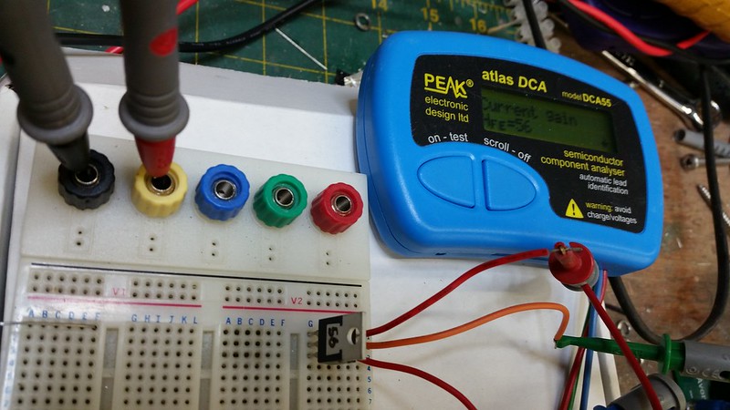
Some useful advice from PD on TR1/2 matching.
. You need a meter with an option for measuring transistor gain (known as HFE).
Measure several transistors, and choose a pair where one is about 10% higher than the other. If you only have two, measure them both, and use the higher gain one for TR1.
Hope thats OK with you PD.
And a link to the discussion we had over on the GB thread
http://www.pinkfishmedia.net/forum/showthread.php?t=168349&page=20
Some great advice and info from Alan
http://www.pinkfishmedia.net/forum/showthread.php?p=2662890#post2662890
and a lovely board shot of his NCC200 build.
http://www.pinkfishmedia.net/forum/showthread.php?t=168349&page=21
--------------------------------------------------------------------------------
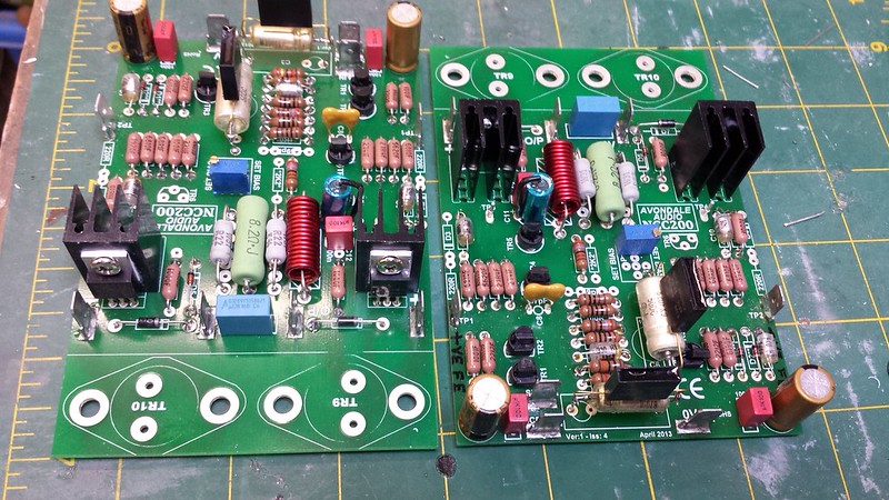
Some more pictures that Ive lifted from Alans awesome build. (Hope thats ok)
Two lovely NCC200 Builds
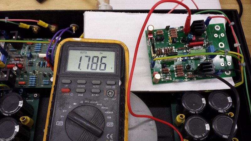
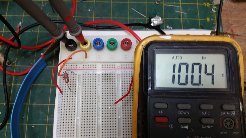
Checking the boards before the OP transistors are fitted using TP3/4. it really can save a great deal of time and expense (and even magic smoke) to check the boards this way as Malcolm has pointed out in his post above. don't waste the chance to test before committing the OP transistors.
Notice that Alan has fitted the PSU connections and BOTH 0V leads.
It really helps the testing process to fit board pins to the test points as Alan has done. Notice no hands near the board are needed with clip leads.
Then just a small gentle turn clockwise and anti clockwise on the bias set trimmer pot should give a change in reading on the multimeter (be gentle with that pot).
if all is well then good to go for fitting the OP transistors.
Great work Alan
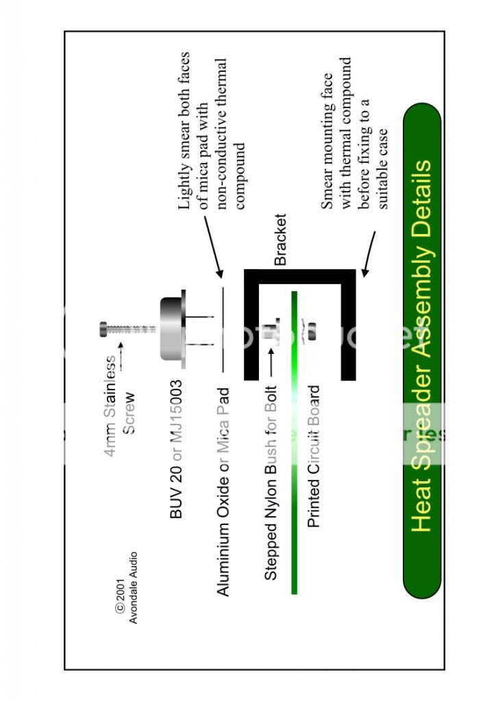
Ive copied these from the circuit diagram above just in case anyone has missed them.
Another really nice build and product description can be found here.
http://www.avondaleaudio.com/NCC200_v1.4.html
Setting up the bias
[/URL][/IMG]
Measuring DC offset

Please note that no speakers should be connected when measuring bias and DC offset.
And as a side note I was sifting through my memory of building the NCC200/Voyager clones and I remember something that nearly caught me out.
C11 68uf 6.3V BC128 cap.
Its polarised
I found the markings a little difficult to read as the ones I had faded a little.
Here is a link to Farnells page.
http://uk.farnell.com/vishay-bc-components/mal212853689e3/cap-alu-elec-68uf-6-3v-rad/dp/1166615
Anyone not sure of how this component orientates to the board should check out the product data sheet located on the above page.
Some great fault finding tips from S-Man
Thanks again Dave
Powered Fault finding
I recommend you insert a 10R to 22R 1/4W resistor in series with each supply lead (between the CAP 6 and the NCC) for switch on and test purposes.
If the NCC is working these will only drop about <1V. If there is a short circuit somewhere the resistors will emit a warning similar to a miniature flare
.If the NCC is pulling too much current but not actually shorted they will give you a smelly warning and limit the current.
Recommended test sequence:
1) Check the supply rails (on the NCC board power terminals and T1 and T2)
2) Check the output offset voltage. 0V means something is wrong, as does >100mV (DC of course). A few mV drifting around slightly is a good sign!
3) Assuming #1 is OK but #2 indicates a problem,then:
4) Check the voltage across the feedback cap - if it is more negative than ~100mV or more positive than 5V switch off immediately.
5) Check the base-emitter voltages on TR3 and 6 (i.e. across the 620R and 68R). These should be about 0.65V.
6) Measure the voltages on Tr1 and 2 emitters (easier to measure on the 100R tail resistors). Should be ~-0.65V, relaltive to 0V.
7) Measure the voltage across the 1K TR1 collector resistor - once again it should be ~0.65V.
8) Measure the voltage between TP3 on 0V, then Tp4 and 0V.
non-powered fault finding
Disconnect the Cap6 and using the ohms setting measure from the + supply terminal on the NCC to the o/p terminal, then from the - supply terminal to the o/p. I am assuming TR9 and 10 are not fitted. Compare the results with the other channel (although of course we can't be sure any mistake is not copied in the other channel).
Check all the parts around the output stage (ohms setting) - !N4004s, 100Rs, 0.22Rs, 1N4148. It's unusual for these parts to fail but we need to be sure that nothing has gone short on the TR7 side, or open on the TR8 side.
Edit: Just thought: you can't have a hard short on the TR7 side otherwise your 100R safety resistor would be charcoal - you have fitted the 100R safety resistors I hope?
TBH non-powered fault finding is tricky, it's often hard to interpret the readings without removing some transistors. Therefore, you another approach in to lift one end of the feedback cap (so you don't damage it with the excess voltage), the amp will still bias up properly, although it will not amplify any audio. Then you can go back to powered fault finding - especially if you have the safety resistors fitted.
If you want to go this way:
1st check the voltage across the 68uF across TR5 - if it's >6V power down and remove it!!
2nd, write down on a schematic the dc voltage on every node in the amp (all relative to 0V) and post it on here.
Option 3: Remove all the transistors and polarised caps. Measure all the remaining components in situ and then replace all the trs and polarise