advertisement


NCC200 GB Build thread

Sorry folks, I need your advise. I get no reading when testing the board. I've powered the board from discharged psu but got no reading between Tr3 and Tr4 on my multimeter. I've turn the trimpot several turns to no avail. I swapped the multimeter. No reading. Where shall I look in first?
Cheers
 
Measure your supply voltages (referred to 0V).
Then measure the output offset voltage (also ref to 0V).

Let us know your readings.
 
Sorry folks, I need your advise. I get no reading when testing the board. I've powered the board from discharged psu but got no reading between Tr3 and Tr4 on my multimeter. I've turn the trimpot several turns to no avail. I swapped the multimeter. No reading. Where shall I look in first?
Cheers

Hi Toni

''Sorry folks'' no need to be. that's what this thread is for.:cool:

should TR3 and 4 read TP3 and 4?

Have you fitted D3/D4 and the associated 220r resistors? even if you are building the Voyager clones they still need to be fitted for the test stage.

A photo of the board may also help.

back and front please:cool:

Hi Dave

''Then measure the output offset voltage (also ref to 0V).''


I'm assuming that this is the first test stage so no OP transistors are fitted ATM but I may be wrong. Anyhow a photo should reveal all (hopefully).
 
Been trying to understand what all the extra bits in the NAP/NCC actually do...

Disclaimer: No criticism of the design is intended, nor any implications on sound quality.

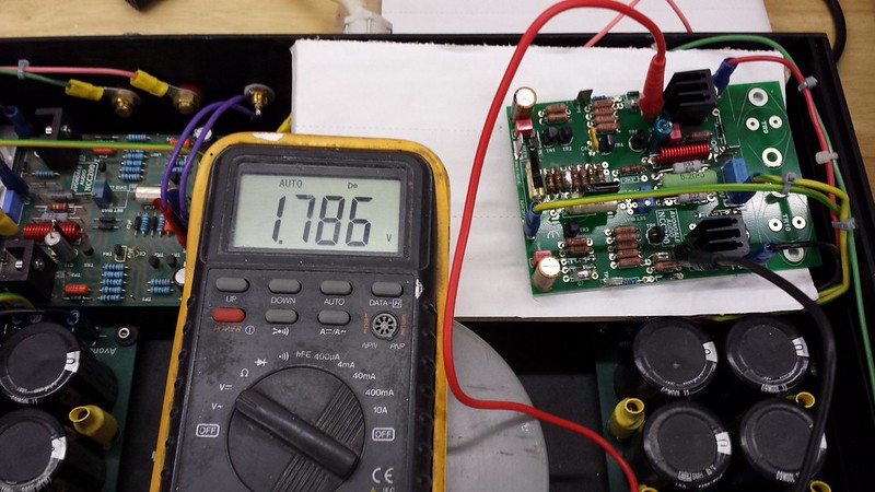
I am running the amp on the bench with 35V regulated supplies, no local decoupling, the RC in each front end supply shorted and no input filter. References are made to this circuit:
http://www.acoustica.org.uk/t/naim/poweramp_pix/NAP250 schematic.jpg
Which is representative of what I am running (of course with no SOA protection).

1) TR2 collector resistor, 22K:
This has no effect on the DC offset as I thought it might. It does however slow the amp down just a bit. This seems illogical given the dominant pole type compensation the amp uses. So it's part of the compensation network (as other have said).

2) The 470pF caps in series with the base of the drivers:
According to the RCA notes these are to improve the transient response, and indeed the one on TR10 base does. The one on TR9 base seems to do nowt.
However replacing the 2 resistors and 470pF combo with a 10R resistor (like most amps do) results in a better improvement. Apparently the 680R and 560R are there to limit current in case of overload, but I'm not convinced they are needed.

3) The 1K and 220pF on the base of TR6:
No testing done on this, but it would appear to be there to 'enhance' the Early effect in TR6, thereby increasing the VAS current at high +ive swings. The 200pF limits this extra current to audio frequencies.

As a general comment the weakness of the amp seems to be the Q-comp output stage. This is sluggish at turn on and the class B drivers don't help (as PD said). The way to side-step this is to bias the amp a bit more than normal - 60mA seems to do the trick. Alternatively shorting all the resistors mentioned in #1 and 2 achieves better results with more normal bias values - ~30mA.

To be honest, some extra bias might help this amp which has rather poor thermal feedback for Iq.

Transient response into a capacitive load is not great and once again highlights the sluggish TR10/12 effect. It is massively improved by using the 0.22 Ohm output resistor like Naim do - this get's rid of the sharp edges in the waveform resulting from Tr12 not being able to turn on quickly enough.


Adding the input filter masks most of the effects mentioned above.


Loop stability looks fine with a wide variety of awkward loads using either the NCC output inductor or the Naim 0.22R. I don't know why Naims are supposed to be on the edge of stability (caveat the lack of LTP emitter resistors will affect the loop stability a bit in the NAP).


Conclusion:
Decent but not spectacular technical performance if built as standard. 0.22R output resistor version is better behaved into reactive loads.

Next steps:
Lash it up with a generic PS, give it a soak test then have a listen. Which, of course, is the only bit that matters!

Hi Dave

Sorry I missed your post which has shown some pretty interesting results.

TBH I’m not sure I’m in a position theory wise to comment on your findings but maybe Les would be willing to go through them and his component choices with you when he has time.


But the posted results, comments and the spirit in which you’ve made them are most welcome.:cool:


I will be interested to hear how your listening tests correspond to your measure ones.
 
When checking the voltage between Tp and 0 it reads a spooky -47.7Vdc and likewise between Tp4 and 0.
Some tr must not be working ????
 
Hi Toni

Nice work but if I may ask a few questions, some of which will be stupid.;)

Are you sure that Your boards are isolated from the heat spreaders? both of the large bolt holes for each of TR9 (Collector pins) and 10 (collector pins) are now connect together on this board (take a close look at the other board that you have and you will notice that) unlike V1.3. So be very careful with that as some things have changed from the last version. i'd take the spreaders off completely and slide some insulation under the board to be sure. Looking at the photo's you've posted I'd say that this is the most likely cause of the problem ATM. So it's possible that you are shorting your +VE PSU through the bolts that your using to fix to the spreader of TR9 to the collector pins of TR10.

tr9%2010.jpg
[/URL][/IMG]

No need for the spreaders to be connected to do the first test IMHO and bad idea full stop.;)

Alan has the right idea.

14816123517_3b85cdaeb4_c.jpg


It also works for me:cool:

Have you checked your leads for continuity? I know :) but it has been known for crimps to become loose or disconnect. You could also check the PSU voltages on the NCC board just to be sure.

I usually crimp and solder to avoid such things.

Great photos but post them on the forum and maybe one a little closer to the Top of the board would make things a little easier.

I find it much easier to test the boards out of the box which allows a closer inspection to be made.

Looking good though and just a little more fettling needed.:cool:

Keep us posted.
 
Just had an hour of listening to my lashups.
Kinell, this is a damned good amp!!!

Hi Dave

Great news.:)

I’m really glad that you are enjoying the sound.

Some people have noticed that they need about 2 weeks to really start singing.

and you still have some nice stuff to add like the VBE boards which bump the sound up to another level IMHO.:cool:

Which OP transistors did you end up going for?

keep us posted.
 
Nice work Dave

Those look like the equally lovely Mundorf caps in your PSU.:cool:

I've been enjoying listening to my new R Core/cap6/Mundorf PSU arrangement burn in (if you believe in such things then you may notice the sound improve over time with the NCC) mmmmmmmmmm

Sounding very good this end also.:)

With IE transformers (just out of shot)?

The BUV are great sounding OP devices to my ears so good choice.:cool:
 
The caps are BHC. I acquired a load of NOS ones, they measure fine for capacitance and ESR etc. even though the date code is 1991.
My mosfet amp uses the same ones. I want to be able to do plug and play comparisons.

The inductors are air cored. I will be comparing these to the ones you sent me. Thanks!!

BTW, this thread seems to be a 2 man show now. Where's everyone else???
 
The caps are BHC. I acquired a load of NOS ones, they measure fine for capacitance and ESR etc. even though the date code is 1991.
My mosfet amp uses the same ones. I want to be able to do plug and play comparisons.

The inductors are air cored. I will be comparing these to the ones you sent me. Thanks!!
BTW, this thread seems to be a 2 man show now. Where's everyone else???

the BHC caps are nice units also.


Good question:)


Some people are going to take a little more time than others which is fine. Some won't post their builds at all that's also fine.


But


It's the people who run into problems that I'm most interested in hearing from as they may need a little advice along the way. Experienced builders such as yourself and others can really play a good role in getting the less experienced over the finish line.


I remember my first build pretty well.


A bread board 6EM7 SE and when running it sounded superb but I needed help to get it playing music.


The help I had got me started and 30 years later I'm still enjoying the thrill of that first switch on with a new build.


In my small experience most newcomers to DIY just need a few basic tips to get them started. How to stay safe, solder a nice shiny joint, organise their work and learn a few bits of basic electronics such as Ohms Law(and if really lucky Kirchoff, Thevenin aaaand Norton ;)).


Anyone who gets stuck with their build please ask.


No such thing as a silly question here.:cool:


So stick around Dave.


The fun is only just starting.:D
 
Shoom
You were just right. The track between holes have shorted the supply through the bolts. Now I'm using a polystyrene board to sit the nCC200. The reading I get puzzles me a bit. Between Tp3 and 0 is -48 while betweenTp4 and 0 is +48. Shouldn't it be the other way around? The connection from PS are right, though. BTW, only 0 volts fromTP3 and TP4.
Have I blown any TR's?
Cheers

PD. I cannot test the other board as the supplier sent a mica cap with 5 times the value and am still waiting for the exact 47pf.
 
Harthold - I recommend you insert a 10R to 22R 1/4W resistor in series with each supply lead (between the CAP 6 and the NCC) for switch on and test purposes.

If the NCC is working these will only drop about <1V. If there is a short circuit somewhere the resistors will emit a warning similar to a miniature flare :).If the NCC is pulling too much current but not actually shorted they will give you a smelly warning and limit the current.

Recommended test sequence:
1) Check the supply rails (on the NCC board power terminals and T1 and T2)
2) Check the output offset voltage. 0V means something is wrong, as does >100mV (DC of course). A few mV drifting around slightly is a good sign!
3) Assuming #1 is OK but #2 indicates a problem,then:
4) Check the voltage across the feedback cap - if it is more negative than ~100mV or more positive than 5V switch off immediately.
5) Check the base-emitter voltages on TR3 and 6 (i.e. across the 620R and 68R). These should be about 0.65V.
6) Measure the voltages on Tr1 and 2 emitters (easier to measure on the 100R tail resistors). Should be ~-0.65V, relaltive to 0V.
7) Measure the voltage across the 1K TR1 collector resistor - once again it should be ~0.65V.
8) Measure the voltage between TP3 on 0V, then Tp4 and 0V.

That's enough to be going on with :)


BTW you can fit the 220pF cap in place of the 47pF, the amp will work but be very over-compensated (=slow).
 
Thanks Dave


Given that the OP transistors are not fitted at the moment then 1/2 may not be applicable.


Useful to have for future reference though so good info.:cool:


But 4-8 are very useful for Toni to use now.


Toni please report back on what you find.


and have a solder sucker (pump) in your tool box.:cool:


Slow patient work will solve the problem.

Another suggestion if the above proves inconclusive would be to finish the other board and test. if it works out OK then you have a reference to fix the other board.

Either way it's going to be fixable so stay with it.:)

Good work James we all get there in our own time and the hare sometimes does loose.:D
 
BTW, this thread seems to be a 2 man show now. Where's everyone else???

I can't speak for everyone else, but I have been lurking in the shadows following as much advice as possible for my build. Shaun has given up a lot of his time checking my build and handing me indispensable advice, couldn't have done it without him and everyone who contributes to the forums :) This is my first ever DIY build so I need all the help I could get!!! :D

Speaking of which, thanks for the advice on testing the NCC200 board!

I'll post some pics when I get closer!
 
Step 4: +12v so seven volt over the limit: I have switched it off. What next? Shall I proceed with the other steps?
 
No, you need to do some non-powered fault finding now:

Disconnect the Cap6 and using the ohms setting measure from the + supply terminal on the NCC to the o/p terminal, then from the - supply terminal to the o/p. I am assuming TR9 and 10 are not fitted. Compare the results with the other channel (although of course we can't be sure any mistake is not copied in the other channel).

Check all the parts around the output stage (ohms setting) - !N4004s, 100Rs, 0.22Rs, 1N4148. It's unusual for these parts to fail but we need to be sure that nothing has gone short on the TR7 side, or open on the TR8 side.

Edit: Just thought: you can't have a hard short on the TR7 side otherwise your 100R safety resistor would be charcoal - you have fitted the 100R safety resistors I hope?


advertisement


Back
Top