
You are using an out of date browser. It may not display this or other websites correctly.
You should upgrade or use an alternative browser.
You should upgrade or use an alternative browser.
NAP 90 versus NAP 160
- Thread starter hollamby
- Start date
Johnny Blue
I made it to 'Member'!
Gone.
Epilogue
So once again, thanks to all who contributed to this.
The 160 is now back in my hands after being sorted and serviced by Darran at Class A. It's sounds great and he's done a good job.
He threw away the capacitors that Johnny Blue and I fitted, saying they weren't up to the job and sounded flat. And started again.
In-between that, there was an unpleasant incident with a bolshy amp repairer which I'm not allowed to talk about on here, but thanks to Darran for retrieving the amp.
At the end of the day it cost:
'perfect working condition amp' from ebay £270
New Capacitors £60
Class A service £215
Delivery x 2 £30
Total: £575
Enjoy the football Johnny Blue.
I won't darken your door again, until the next time.
The End.
Johnny Blue
I made it to 'Member'!
Oh, mate, this is nearly as bad as a Rob Green fumble...
Mignun
pfm Member
An interesting thread. Glad you finally got the 160 fully sorted. In the end it's worthwhile getting things done properly.
One possibility regarding the unusual pre supply: The first 160s didn't have a pre supply fitted. It's possible that at some point in its life this one had somebody retro-fit one. Done poorly by the look of things. The wiring and soldering on that DIN socket was shocking!
One possibility regarding the unusual pre supply: The first 160s didn't have a pre supply fitted. It's possible that at some point in its life this one had somebody retro-fit one. Done poorly by the look of things. The wiring and soldering on that DIN socket was shocking!
coltrane
electrobaroCKjazzer
a perhaps quite obvious question for the ones in the know, but here we go: where to measure bias on a NAP160 main board, I wonder? I am aware that there is that trim pot, that's okay with me, but I just have no idea as to where to put the tips of my multimeter? also, is there a chance to adjust DC offset on the output, too? if so, where, please? I'm asking as on my amp on one channel it's merely 7.5mV while on the other it's 27.5mV. your advice will be much appreciated. to note, otherwise the amp just sounds great, I only want to make sure that it performs at its best ")
Gaius
pfm Member
This is a very old thread and I've not read the many pages but the title caught my eye.
NAPS 90 v 160
Well that's a slam dunk and if anyone says different they are quite deluded.
Playing my 160 right now, I might give it up for a NAP300.
Is that clear enough?
The 160 being the very clear winner, like miles down the road; I mean miles....
NAPS 90 v 160
Well that's a slam dunk and if anyone says different they are quite deluded.
Playing my 160 right now, I might give it up for a NAP300.
Is that clear enough?
The 160 being the very clear winner, like miles down the road; I mean miles....
misterc6
Wasted and wounded, it ain’t what the moon did
a perhaps quite obvious question for the ones in the know, but here we go: where to measure bias on a NAP160 main board, I wonder? I am aware that there is that trim pot, that's okay with me, but I just have no idea as to where to put the tips of my multimeter? also, is there a chance to adjust DC offset on the output, too? if so, where, please? I'm asking as on my amp on one channel it's merely 7.5mV while on the other it's 27.5mV. your advice will be much appreciated. to note, otherwise the amp just sounds great, I only want to make sure that it performs at its best
This possibly belongs in the DIY room but here goes:
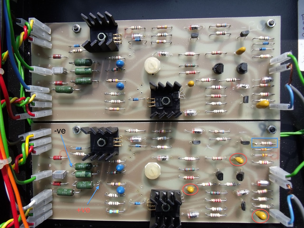
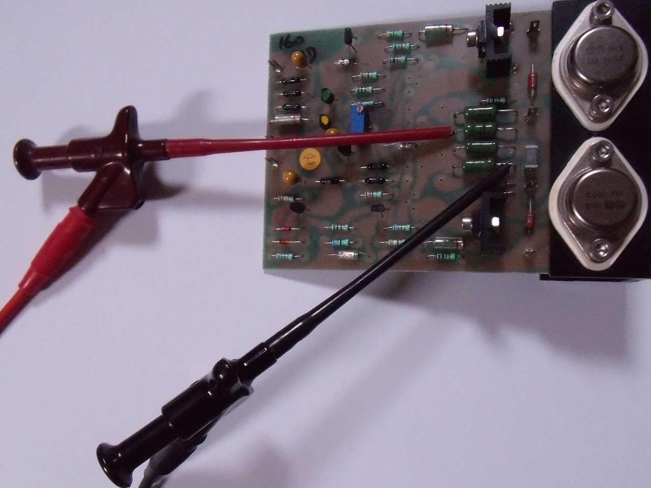
All tests should be carried out with no load or speakers attached and no signal input. The probe positions for bias checking/setting are indicated by the arrows. You should set for 7.0 mV with the amplifier cold. Use probes that can be clipped on as in the photo below, of a later board, as waving naked probes around this area of the board can be terminal.
Someone should make a sticky about d.c. offset.
Offset does not adversely affect the performance of the amplifier and it doesn't matter if the offsets are different on the left and right channels. Neither does it matter if one is positive and the other negative. The problem with offset is that if it is too high it can damage your speakers. The aim is to have it below +/- 30 mV (so your readings are OK) but I'd start to worry if it were over 100 mV.
There's no adjustment for it but the resistor in the blue rectangle has an effect. In early production Naim used values between 470R and 750R and you shouldn't be surprised to see different values on your two boards. If the amplifier had ever been serviced by Naim they would have changed both resistors to 560R and this is worth doing if it hasn't already been done.
The most likely cause of your slightly high offset on one channel is that one or more of the tantalum bead capacitors in the red ovals have started to get leaky. Again, in a routine service, these would all be changed. Use good quality (AVX or Kemet) replacements of the same value as those fitted. Use the existing polarity for the one close to the driver transistor heat sink but for the other two you should ignore the existing polarity and put the positive leg towards the terminal on the edge of the board.
HTH,
Malcolm
coltrane
electrobaroCKjazzer
sure, highly agreed
to add, my yesterday query was partly resolved as I in the meantime gathered info from the net that bias can be measured on the .22R green resistors at the north of the PCB and set to 4.5-5.0mV. now, I did it but still wonder if it's okay this way? to note, on one channel bias was 4.0mV while on the other it was 4.3mV measured as above.
moreover, my other question remains still as to how to adjust/settle the DC offset, please?
coltrane
electrobaroCKjazzer
just a final question, Malcolm, please. that is, on my main PCB, as I also gathered form the net, the SOA was disabled by lifting one leg of the diodes (in your picture they're there in blue) but the adjacent trannies were left there untouched. as I, however, see that those diodes are still there on your PCB while the trannies got removed, I thus wonder if these diodes are needed for some task in the circuit, or you were okay by just removing the trannies and left the diodes in situ as they do no harm?
misterc6
Wasted and wounded, it ain’t what the moon did
There are many ways of disabling the SOA. I think lifting the diodes is suggested because one leg of each can be cut, and resoldered later if required, without lifting the board. Removing the transistors achieves the same result although I prefer removing all twelve of the SOA components.
Malcolm
Malcolm
misterc6
Wasted and wounded, it ain’t what the moon did
one more question - excuse me - is that must these replacement caps be tantalum ones, or can they be e.g. MKP/MKTs, I wonder? also, there are 2pcs. 3.3mF 50V elkos on the underside of each main PCB - can they be substituted for MKP/MKTs as well?
The tantalum beads are one of the main contributors to the Naim sound. You could try other types if you like especially for the feedback capacitor. There has been much discussion about capacitor rolling on here. Les favours solid aluminium for the input and bias capacitors. I prefer the sound that tantalum gives although wet tantalums are a good option in the feedback position. The Elkos must be a non standard later addition.
gary yeowell
pfm Member
The 160 is one of Naim's best, and wiped the floor with a new 140 i had some years back. Service required....
Maxbertola
pfm Member
I have owned both, in different but not very far apart times.
First came the 160. I had a Denon CDP of mid/high class and magneplanars, and an Audio Innovations Classic 25 that drove the Magnepans feebly but with huge musicality.
It was somewhere in the first half of the 90s.
The 160, in comparison, sounded leaner, more precise, more aseptic. It drove the Magnepans obviously better but had none of the rich, full sweetness of the AI. It must be said, though, that I had no preamp for a while and drove the 160 directly from the variable output of the CDP.
The 90 came a few years later, with another setup. I had 42/90, a Denon CD3560 (almost top level then), and a pair of small, hand made BBC-style mini monitors.
In spite of this, I can recall that my impressions of the sound of the 90 were very different from those of the 160; in my opinion, Naim had already started to voice their power amps differently with the 140, that I also had had, making them more full, more easy sounding than the classic breed.
I can understand the OP's impressions; if I judge by memory, and with all the obvious limitations of time elapsed, his impressions match mine. I wouldn't say, though, that the 160 has lesser bass, but that the 90 is more 'friendly' and less controlled.
M.
...Someone should make a sticky about d.c. offset.
... There's no adjustment for it but the resistor in the blue rectangle has an effect. In early production Naim used values between 470R and 750R and you shouldn't be surprised to see different values on your two boards...
Malcolm
Hi Guys: another new NAP160 owner here.
This is actully good to know, I've started on rebuilding my recently aquired "bolt-down" 160. Mine has this resistor variation. 560 for the right board and 750 ohms for the left hand board. The left hand board also has the 750 ohm resistor soldered onto what appears to be the remains of the original 560 Ohm resistor's "cut-off" leads so as to avoid lifting the circuit board.
I originally thought that this was done by a dubious repair man, however looking at the schematic I can see how it could be used to trim the offset on the input pair. I was about to replace the 750 ohm resitor but i have more than acceptable DC offsets on both channels so now I think I'll leave it as it is.
I am still curoius though, two resistors that appear to be part of the SOA limiters alos appear to be different between the two channels. Is this also a normal variation or an error.
Thanks for any Ideas.
LPSPINNER
misterc6
Wasted and wounded, it ain’t what the moon did
The most often seen NAPA board schematic has a number of anomalies/errors when compared to production boards. These include the input and feedback capacitors being shown with the incorrect polarity.
In the upper half of the schematic the SOA transistor has 47R and 100R resistors on its base, in the lower half the values are 43R and 120R. This is due to a small difference in the topology of the two halves of the circuit. These values are confirmed in an official Naim schematic dated 1994.
On early boards the resistor from the emitter of TR3 to the negative rail appears to have been 'select on test' (SOT) and you often find one soldered to the cut off legs of an earlier resistor. The later official schematic shows the value of this resistor as 620R.
Malcolm