
a.palfreyman
pfm Member
Goodness me. That's a healthy stock! (I'm a cheapskate at heart ") )
)
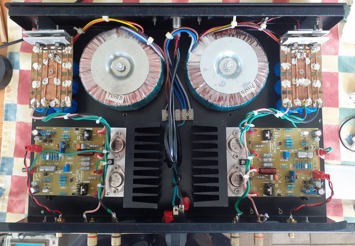
))I'd be interested to know more about this as I have had to route my front end 0V returns via different paths for minimum rectifier noise pick up. Mine are actually Clairtronic transformers (one per amp board) but be interesting to know how to detect stray field.^ Nope, Naim didn't use that Talema/Nuvotem wiring convention. They tested each one for stray field and wired them for the minimum, they all have letters on top denoting the wiring convention to be used.
This gent in New Zealand has some tips re orienting toroidal transformers for minimum noise pickup. He had been documenting his NAP250 clone project via a series of videos. I just stumbled upon this particular one yesterday whilst looking into Talema's in particular.Only had bits of listening here and there as I'm struggling with the bl00dy bathroom refurb...
Anyway, now I have different interconnects between my CD and pre which appears to have solved the upper mid 'emphasis' I'm quite liking the KAs bypassed with 0.68uF MKS2.
Thanks to @Craig B I stumbled across this WRT talema transformers:
I'd be interested to know more about this as I have had to route my front end 0V returns via different paths for minimum rectifier noise pick up. Mine are actually Clairtronic transformers (one per amp board) but be interesting to know how to detect stray field.
Now trying to decide if £33 on a pair of Charcroft z foils will be worth it as that's a LOT of 'normal' 1% metal film resistors...