That’s a bit harsh - why awful? Looks OK to me, even if not original - and maybe it sounds better? Or is it just sacrilegious to modify such circuits? I’m always modifying stuff, sometimes better, sometimes worse….
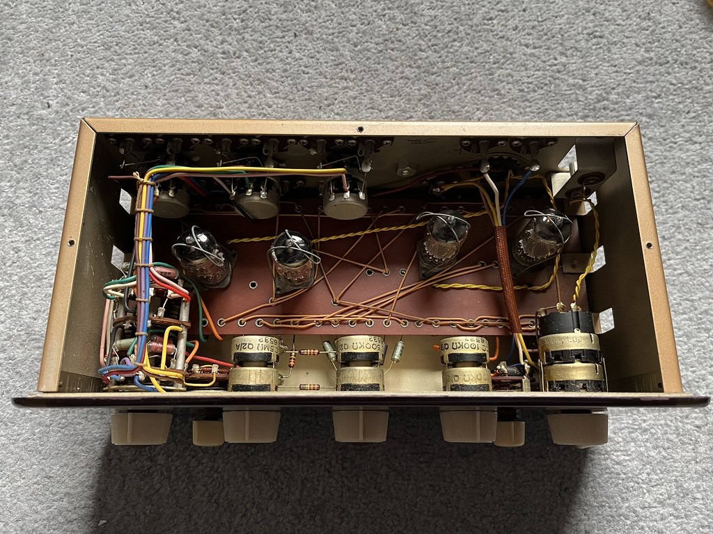
Not harsh at all, just pointing out the facts. It has been poorly done, check out the original image that Tony posted and compare. If you are going to rebuild one of these amplifiers then at least do it, or give it to someone who can replicate it to the same standard as the original.
Here are some of the reasons:
1. Incorrect capacitor values...
2. Poor quality plastic caps used in the signal path...
3. The use of wire wound resistors for the cathode bias...
4. The use of cheap metal film resistors...
5. Incorrect value power supply capacitors...
6. Incorrectly fitted power supply resistor...
7. Poorly fitted power supply capacitors, one left flapping about in the chassis...
8. Mains wiring a mess and poorly soldered...
9. Components not centred in their position on the circuit board...
10. An extra hole drilled in the top of the chassis and an RCA socket fitted...
11. The RCA socket poorly fitted and wired up...
12. Circuit board tags bent and not straightened up...
13. Circuit clearly altered from standard...
14. An IEC has been fitted and just wired on to the original Bulgin mains socket...
15. Poor quality parts have been used which will cause a significant degradation in audio performance...
16. PVC wiring burnt and left bent and straggly...
I could go on...
Basically a butchered job and now worth significantly less money than if it had been kept standard, or done sympathetically by an expert.

")