advertisement


Leak TL/12 Plus / Point One Plus

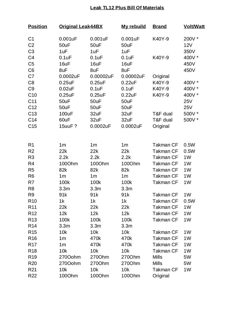
Thanks. I’ve sourced some K40Y-9s for C1. 200V seems the only ones available, but I think that’s what’s in the S20. R5 is interesting, no idea why that is wrong. Both schematics say 82k there so no ambiguity. I’ll leave C15 and C7 alone for the time being if they are likely good. Aside from those two, the 0.22uF, 0.1uF and 1000pF K40Y-9s I think the rest are all polarised electrolytics. I’ll post another proper bill of materials before putting in an order as I’m still a little confused as to voltage and Wattage.

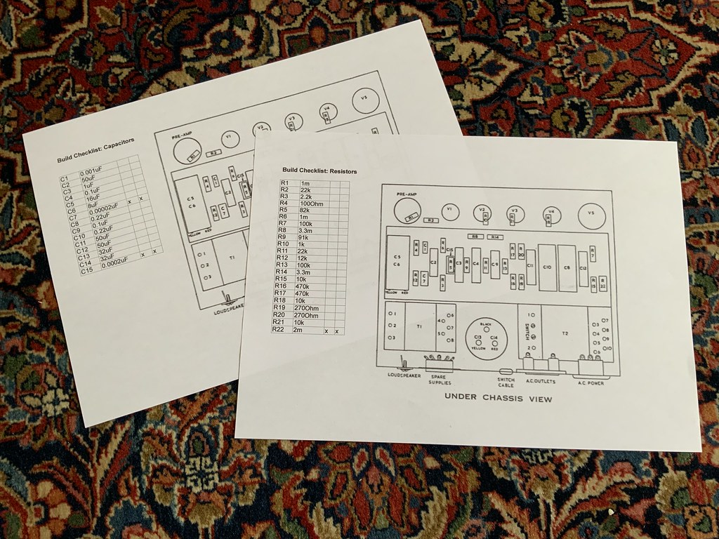
For me this is the hard bit. I basically need to reduce the whole process to an Airfix kit level of simplicity in advance. Once I have it at a ‘solder this bit here this way round’ level of documentation I know I can do it, and do it neatly! I’m not doing anything until I’ve got that nailed down, so bill of materials first!

Any views on fuses? These have the very old little fuses in the voltage selector plugs in the top of the mains transformers. They are 2A and both rather crusty and corroded. I’m pretty sure they are original, i.e. they didn’t offer any protection when the amps apparently got into trouble. I’ve ordered some new fuses (15mm ones do fit, despite not being ‘right’), and I’m thinking of trying a 1A fuse there to see if it works (I have some). I assume the 2A was for the thing under full load, e.g. also powering a preamp? I guess it will either blow or work! I’ve got 2A fuses on the way so nothing lost if it does.

I also notice in both these amps Harold’s magic green resistor couldn’t ‘safety drop’ as the eyelets aren’t cut through the way they are on my S20. I’ve no idea if it ever actually worked/desoldered itself in a failure mode, but it clearly can’t here if it is properly through the tag-board eyelets. I’ll likely address that.
 
Might also be worth adding HT fuses of some kind - something like a 160mA quick-blow / F. Lost count of the times an HT fuse has saved me from an unwelcome BBQ.
 
Might also be worth adding HT fuses of some kind - something like a 160mA quick-blow / F. Lost count of the times an HT fuse has saved me from an unwelcome BBQ.

Is that what you are doing with the red wire from the smoothing cap and fuse under the output transformer here? I assume the other red wire is just tucked under the board for neatness, or am I missing something?
 
Is that what you are doing with the red wire from the smoothing cap and fuse under the output transformer here? I assume the other red wire is just tucked under the board for neatness, or am I missing something?

Can't remember exactly how I wired it but either the fuse is just in line with the output transformer centre tap or in line with the whole HT - really it's just the output stage that needs fusing, the rest is inherently current limited by virtue of the anode resistors.
 
Thanks, I’ll look into that later. I’ll just get them working in totally standard form first and then if I decide to use them as a regular amp consider adding more protection. I plan to build a simple dim-bulb setup before applying any power after the rebuild which should give some protection against any idiocy on my behalf. I’ll be doing the diode thing too (I’ve got them now).
 
Thinking more about fuses it occurred to me that the Stereo 20 only uses a 1A fuse, so I really don’t understand why the far smaller TL12+ specifies 2A. The Stereo 20 has a whole extra power amp channel and would be expected to power a stereo preamp which I assume has twice the valves in it. I’m definitely going with 1A here. If they blow I’ll rethink.

PS I’ll publish a bill of materials for scrutiny in a day or two. I’m actually building a dim-bulb tester first, so have been ordering the parts for that.
 
51090092965_3cc0d5db4d_b.jpg


Here’s an updated materials list, I’d very much welcome any error-checking of the ‘My rebuild’ column or other suggestions as I’m about ready to stick an order in and obviously want to buy the right stuff!

In the capacitor voltage the * indicates stuff I either already have already (e.g. the K40Y-9s) or know I’m buying, the other values are read off components actually installed in the amps, i.e. they are the minimum voltage I’ll select when ordering. I think I’ll go for F&T as far as I can as HFC have their axials and they seem very well regarded in the guitar amp community.

PS I know some are not a fan of my ‘bolt an F&T 32/32uF to the bottom of the big smoothing cap’ thing, though just view it as an entirely non-destructive temporary state that can be revisited or revised easily at any point in the future. It will certainly get the amps up and running!
 
I took the resounding silence as a huge endorsement of my list and I’ve placed a “reassuringly expensive” order at HiFi Collective.

Resistors: I got everything in my list above exactly. For the 3.3M I couldn’t get Takman so I’ve gone for two sets whilst I decide; some 0.5W metal film as a fall-back, and some ancient Allen Bradley carbon. My understanding of what R8 and R14 do is sketchy, but I think it may be to prevent extreme HF oscillation or something like that. If ‘ballpark’ is close enough I’ll use the carbon, if not I’ll use the metal film. I’m open to advice here (and everywhere).

Capacitors: It doesn’t seem to be possible to buy 50uF anymore, so I went with 47uF for C2, C11 & C12. I assume this should still be within the tolerance which was pretty wide on the originals IIRC. I also wasn’t able to get exact values for C5 & C6, which are the large green dual cap at the far end of the amp, I went with 22uF and 10uF instead of the specified 16/8uF. I notice Radford Revival used 22uF for both, so 22uF is clearly safe here. I may replace the 22uF with a 16uF when they are back in stock, just to get closer to original spec. All these electrolytic caps are F&T. I was unable to find any 350V 1uF electrolytics so ended up going to eBay for that one and found some Philips 1uF 385V. I’m a little worried here as they are likely NOS (I think Philips rebranded as Vishay ages ago), but hopefully they are ok. I bought a handful of them so I’ll pick the two closest to 1uF, though I have no way of testing for leakage/ESR. I’d take NOS Philips over new Chinese though!

If anything here looks off at all please highlight it. As stated upthread I need to get this down to an ‘Airfix kit’ level of simplicity. I need to catch any bugs here at the specification stage as I don’t have the debugging skills to get it wrong and then correct it later! If I have the right parts I am confident I can put them in the right place/right way round!
 
This site contains affiliate links for which pink fish media may be compensated.
I’m no expert, but have been doing a lot of reading on resistor type choices. As always it seems to be an even split of objective and subjective opinion, and I must say these days I’m increasingly leaning towards the former camp. FWIW in grid to ground positions - the 3M3 - I’ve chosen metal film for lowest noise. For the grid stoppers, some say you need to use carbon comp. Morgan Jones being one of them in his ‘Building Valve Amplifiers’ book. Others say modern carbon or metal films are fine and will not provoke instability. I’ve used Takman for my Stereo 20s grid stopper.

Cap choices look fine, and remember the tolerances for electrolytic caps is pretty huge anyway. Not sure about using NOS for the 1uF though unless you can test them. Might be an idea to ask Will of Radford Revival what he uses there.
 
I’ve likewise read conflicting ‘objectivist’ perspectives, the most worrying being that apparently a lot of modern resistors simply aren’t designed for the high voltages found in some parts of valve amps!

The ‘subjectivist’ reports seem pretty consistent across Leaks, Quads and vintage guitar amps; that if you rebuild using modern plastic caps and metal film resistors the results tend to be dry, lean and bright sounding compared to using more period-correct components. I’m sufficiently convinced by this after playing around with crossovers etc. If I could find a known stable and future-proofed supply of carbon comps I’d have used them throughout. A bit of noise wouldn’t bug me, though a thin and bright sound is my idea of hell, so that is the way I align my priorities. As I see it carbon film are the closest to that I can be confident with.

My Stereo 20 is Takman carbon film throughout aside from the really big 270 Ohm (the ones I’ve gone with Mills for the TL12s) and some metal films in the 3M3 locations. The ‘grid stoppers’ are I assume R16 & 17 in the TL12 and Takman CF have proven reliable in the Stereo 20 in this location so far. That amp has many, many hours on the clock since the rebuild now. It is in regular use.

PS I’ll be needing some mains suppressor (X class) caps to prevent switch-off thumps I guess, though I’ll do that last. That certainly sorted the S20.
 
Yep it's an opinion mine-field. No matter what one does, somebody will pick fault with it, others will agree with one’s choices etc. At the end of the day, so long as the amp is working safely, it hasn’t been hacked around, and the user is happy with the sound, then it’s another classic rescued as far as I’m concerned i.e. it’s all good.

As you know I’ve tried both approaches, the rebuilding with ‘perfect’ modern components (i.e. metal films throughout, polypro caps etc), and the carbon comp, carbon film and paper in oils approach. This time I’ve been doing an awful lot of reading about exactly which positions are most likely to ‘colour’ the sound more than others, and to use carbon films there to ‘voice’ the sound a little (or add a little sweetening distortion, as some might say), subjectively, and use metal films elsewhere for lower noise. So this time around I've chosen the middle road for my Stereo 20s build, and it’ll be interesting to see/hear what the end result is like... It’s an amp I’ll be keeping forever, as it belonged to my Uncle, so for once I’m not concerned with resell value in this instance, I’ll be rebuilding purely to satisfy my own taste.

The beauty of these amps is that it’s very easy to change components without much hassle if one isn’t happy with the rebuilt result.
 
Agreed. I’ll be very interested to watch your progress, the Stereo 20 thread has to be due some pics by now! I’m sure it will be a stunning amp and I’m fascinated to see what you think vs. the Quad IIs.

My rebuild approach is very simple and non academic. I just want as close to stock as I can achieve safely and reliably. I’m trying not to overthink it, but neither am I interested in saving a quid here and there (the HFC bill last night was £127 and that’s not everything, e.g. the K40Y-9s, Bulgin connectors etc etc). I also don’t want to fill it full of absurd boutique audiophile stuff either. I’m trying to achieve a credible high quality rebuild that will sound great and if anything add value (so many rebuilds subtract value, in fact I’m seeing a disturbing trend on eBay not to even show the underside! Who the hell would buy one of these amps without carefully scrutinising the work that had been done?!).
 
Yes, I’ve moved away from audiofoo components. The odd Takman or Kiwame here and there is as far as I go now, and the Russian paper in oils. Everything else is RS or Mouser. Reliability (particularly when running collectable and now lol-pricey Mullards) is just as important to me now as the sound quality.
 
51092044497_8e78438059_b.jpg


Another small step, some thin 6 Amp cable turned up today so I’ve made the mains leads. I’m in two minds about Bulgin connectors; a) they are bakelite so obviously totally cool, b) they are totally lethal. Anyway, they are what they are. I noticed when googling ‘Bulgin plugs’ a while back, as one does, a site Mullard.org, who seem to have no relation to the new production Russian valves reusing the name and are more a NOS spares type place had some military-spec Bulgin rubber strain-relief going, so I grabbed a few. This addresses a lot of what triggers me about Bulgin plugs and makes them a heck of a lot safer. It necessitates using a fairly thin cable, but they are only 6A rated plugs anyway, plus the Leaks have either a 2A or 1A fuse so no need to go crazy. The 6A cable I bought is a very tight fit in the strain-relief and needed lubrication to even get in, as such they are very good and solid. Best Bulgin leads I’ve ever seen! I’ve fused the MK plugs with 5A fuses.

FWIW I find it far easier to wire up Bulgin leads by totally disassembling the Bulgin plug, i.e. unscrew the three sockets from the front of the plug (easy if you have the right size screwdriver). Then just screw the now free terminals to the cable, and finally reassemble the plug. This seems far less frustrating than faffing about with bare wire in cramped locations.

PS Be very wary of Bulgin wiring diagrams found on the internet as some are wrong reversing the L and N. The correct orientation is actually printed on the inside of the plug.
 
The first Leak TL12.1 I bought for a fiver in Notting Hill Gate Record and Tape Exchange was missing a KT66, I guess someone stole it came with carbon resisters fitted in the wrong circuit.

When tested after missing valve replaced sounded very dull and laid back.

I spoke with the dear departed, Dennis Trickett about the problem, he said their should be "Morganite" resistors where the carbons were, once replaced did the trick, lovely sounding classic.

Morganite Resistors...

https://www.google.com/search?q=Mor...hUKEwjbws_k0OLvAhXc_rsIHZhzBHQQ4dUDCA0&uact=5

A friend had a vintage Wurlitzer 1015 juke box amplifier rebuilt by a TV engineer just before he moved from South Africa to England, he complained that his beloved had lost its soul, a proper rebuild with new old components bought its soul back.

wurlitzer_1015_main_540x.jpg


I have read in Hi-Fi mags many times that Metal Film resisters sounded glassy when fitted as replacements.
 
Nice work on those power leads Tony. Have just ordered myself one for the Stereo 20, and one as a spare. Might order some cotton covered mains cable from Okbo Lighting on the bay too, for a little extra vintage mojo.
 
I was rather tempted by the cloth covered stuff as I used some of the braided type when restoring my ‘50s Anglepoise 1227 lamp and it looks exactly right, just as it should. I’m paranoid about Bulgin connectors though, probably irrationally so as I got a rather scary jolt from a guitar amp back in my 20s (from a lead I had absolutely nothing to do with making), so when I saw these strain grips I thought I’d go that route. I’m really pleased by how tight the 6A cable I selected went in, it certainly isn’t going to come loose. I’m not going to try it as I don’t want to have to make the thing again, but I suspect you could pull the plug out of the amp by the cable now.

The Bulgin connectors really are badly designed IMO. Cable grip is pretty much non-existent and the terminals so close to the rear hole it takes comparatively little movement to fracture the cable so it comes loose, potentially live in your hand! Obviously it is of little issue in a static home audio scenario, but these connectors are on the back of every classic Marshall, Vox, HiWatt or whatever UK guitar amp and they are absolutely not road-worthy IMHO. I notice there is actually an IEC socket that will fit in a Bulgin chassis hole with no drilling (Mullard.org). I’d unquestionably do that with a guitar amp I was gigging. Non-destructive, reversible, so will lose none of the amps’s resale value, and way, way safer. I’m not bothered with home audio, if the plug is wired properly and treated with respect it will not bite you.
 
I actually bought one of those IEC Bulgin replacements when I was briefly considering not using the original socket for increased safety. Didn’t quite fit in the hole in the Stereo 20s chassis though. But as the originals are fortunately in fine condition and I now have that cable gland on the way should be fine. Before your post I was going to just use adhesive heat shrink which would likely have done nearly as good a job too.
 
51094285937_4ec6e4cc77_b.jpg


In an attempt to pretty much idiot-proof things I’ve printed out layouts and a checklist. I’ll go through and mark the capacitor polarity manually from the existing amps. My plan is to actually write on the resistor bags ‘R1’, ‘R2’, ‘R17 & R18’ to again reduce complexity and margin for error. My colour sense is not good enough to identify by rings, so I’ll check with a meter what is in the bags (I assume they come in bags) is what they say it is.

As to process I think I’ll strip everything off the first amp’s board so I can clean it up a bit and then build that amp up fully, test it works, and only then touch the second. That way I always have a visual reference point, the original for the first build, the (hopefully) working first build for the second. By the layout of the board it makes sense to do the resistors first, then caps. Just more space to work that way.

I really am trying to make this as much like Airfix or Lego as possible! Any advice as to how to further simplify/idiot-proof would obviously be most welcome.

PS I have no idea how R22 got screwed up, I never typed 2M! It was a simple cut and paste from the spreadsheet I linked upthread! It’s the big green one so no issue, they are staying put, but I’m baffled. I must have leant on the keyboard or something.
 
You should check the number on the output transformer and use exactly the same value resisters and capacitors as listed for that circuit/transformer. So if the amp is original, use exactly the same part values as used by Leak when they built it.


advertisement


Back
Top