Craig B
Re:trophile
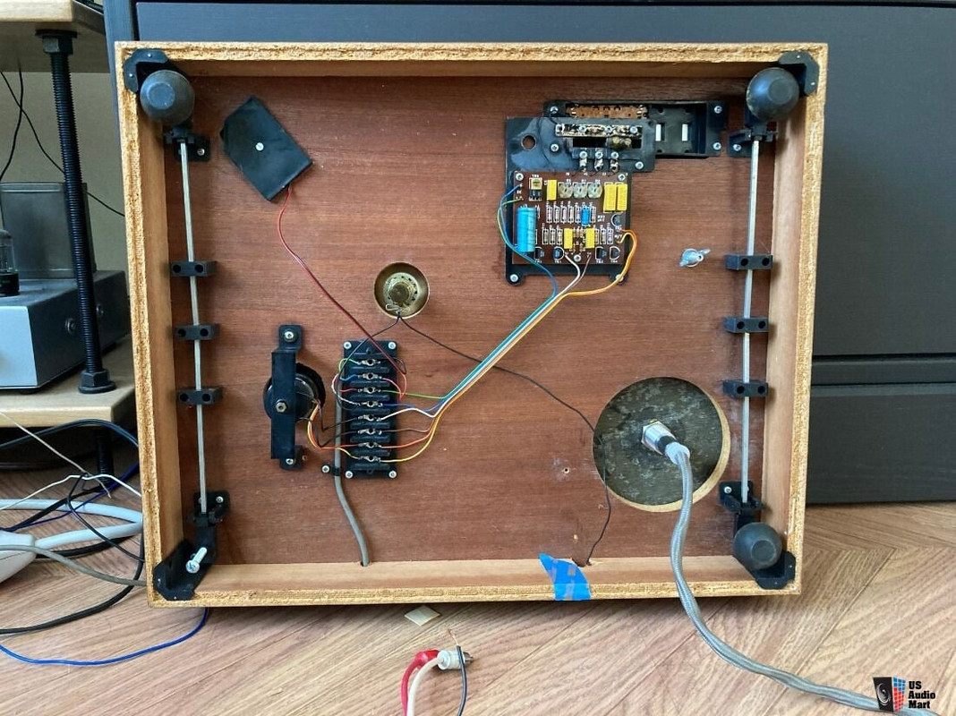
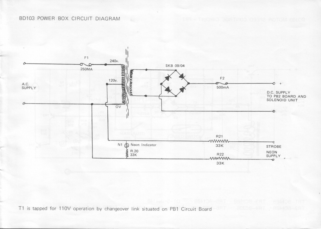
Looking at the power supply schematic, both the external power supply indicator neon and on deck strobe neon are powered from the 120VAC tap on the primary side of the transformer. As such, the strobe light should illuminate immediately upon switch on of the external supply. Note the voltage divider with 33k resistors either side of the strobe neon which takes the 120VAC down to 60VAC. This could be tested for at the terminal strip within the deck without having to delve into the PS. The relevant terminals will be the two that connect the power supply umbilical to the strobe light box. An unusually low reading will likely be down to one or both of these resistors having drifted off spec. Conversely, 0V at these terminals could be down to the power supply inlet fuse having blown, or one or both resistors having failed open circuit, or a bad connection between supply and terminal strip. All easily traced with a multi-meter.
Notes:
Notes:
- The on-board motor servo control circuit has nothing to do with the operation of the strobe. This is simple electrics, not complicated electronics.
- The 250mA fuse at F1 also protects the AC side, so, in addition to the strobe not lighting, if the motor won't turn it is likely that this fuse has blown within the power supply. The line drawing of the PS indicates that this fuse (and the DC side output fuse) are on the PCB within.
Last edited: